Forces in Simple Bar Structure Apparatus | FrixoDynamics FX-512
Product Overview
A CE-certified precision laboratory apparatus for engineering experimentation and technical education, manufactured by Scientico India to ISO 9001:2015 standards. Supplied with calibration certificate, operation manual, and complete export documentation. Designed for Forces and Friction laboratories in engineering colleges and technical institutions.
[email protected]
Technical Specifications
| Parameter | Specification |
|---|---|
| Model | FrixoDynamics FX-512 |
| Number of Bars | 3 (2 rafters, 1 adjustable tie) + 1 spare |
| Rafter Bar Length | 440 mm (fixed, x2) |
| Adjustable Tie Length | 440 mm / 622 mm / 762 mm |
| Node Discs | 3 |
| Force Gauges | 3 (one per bar) |
| Force Gauge Range | 0 – 100 N |
| Force Gauge Graduation | 0.5 N |
| Force Type Measured | Compression (rafters) and tension (tie) |
| Angle Configurations | 60°-60°-60° / 45°-90°-45° / 30°-120°-30° / 30°-30°-120° |
| Support Conditions | 1 fixed node, 1 longitudinally free node (bearing-mounted) |
| Base Frame | Aluminium section, 1 m scale with 1 mm graduation |
| Bar Connection | Quick-lock node engagement |
| Weight Set | 1 x 1 N hanger, 1 x 10 N, 2 x 20 N |
| Scope of Delivery | 1 experimental unit, 4 bars, 3 node discs, 3 force gauges, 1 set of weights, 1 measuring tape/steel rule, 1 instructional manual |
Key Features
Key Features
- Three individual force gauges (0–100 N, 0.5 N graduation) provide direct measurement of internal bar forces in each member simultaneously
- Adjustable tie bar (440 / 622 / 762 mm) enables four distinct truss angle configurations without requiring additional components
- Quick-lock node disc connections allow rapid, tool-free reconfiguration of the truss geometry between experiments
- Two support conditions, one fixed and one longitudinally free with bearings, accurately replicate standard simply supported truss boundary conditions
- Sturdy aluminium base frame with integrated 1 m scale (1 mm graduation) for precise geometry recording
- Supports three parallel methods of force determination: direct measurement, method of joints, and graphical force polygon
- Compact bench-top design requiring no wall mounting or clamping
- Supplied with spare bar, additional node discs, and a complete weight set for full experimental flexibility
Applications
- Direct measurement of compressive and tensile bar forces in a statically determinate pin-jointed truss
- Calculation of bar forces using the method of joints
- Comparison of experimental, analytical, and graphical force determination methods
- Investigation of the effect of truss geometry on internal force distribution
- Study of force resolution in a single-plane statically determinate structural system
- Undergraduate laboratory practicals in structural mechanics, statics, and civil and mechanical engineering
- Demonstration of roof truss structural behaviour for introductory structural engineering courses
Construction and System Design
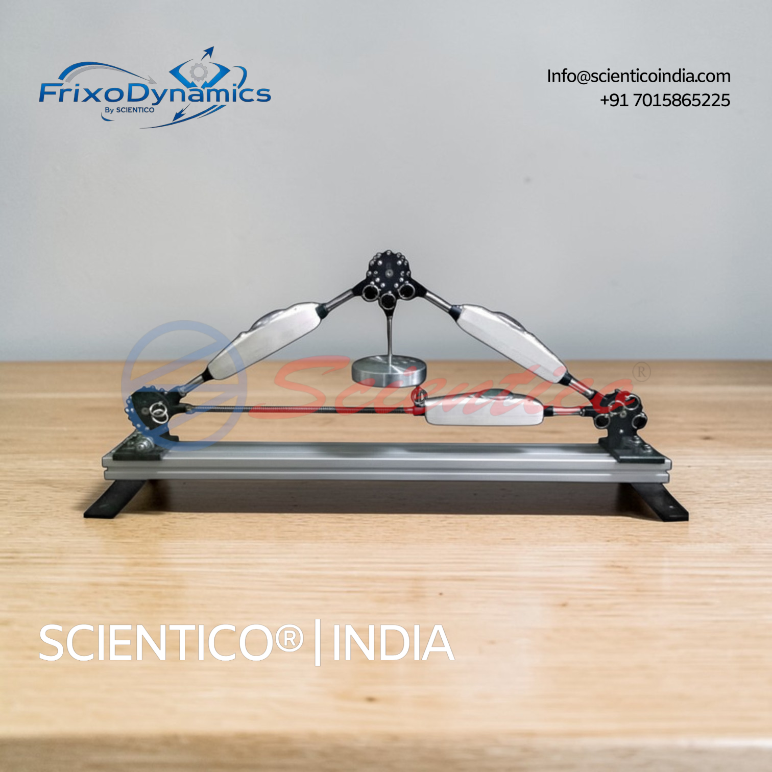
The FX-512 is built on a sturdy aluminium section base frame fitted with an integrated metre scale graduated to 1 mm. Two of the three node discs are clamped to the base frame as supports, one fixed in all directions and one free to move longitudinally on bearings, replicating the roller support condition of a standard simply supported truss. The third node disc forms the apex of the triangular truss and is left free to carry the applied load through the weight hanger.
Each bar engages with its node discs through quick-lock mechanisms, allowing the truss to be assembled and reconfigured rapidly. The two rafter bars are of fixed 440 mm length and connect from the apex node down to the two support nodes. The adjustable tie bar connects the two support nodes horizontally and can be set to three discrete lengths, 440, 622, or 762 mm, each corresponding to a different truss apex angle. This produces four available angle configurations: 60°-60°-60°, 45°-90°-45°, 30°-120°-30°, and 30°-30°-120°.
A force gauge is attached at the midpoint of each bar. These gauges are direct-reading mechanical instruments calibrated for both compressive and tensile forces, displaying values in Newtons with 0.5 N resolution. External load is applied at the apex node using a hanger and dead weights. The measuring tape or steel rule is used to verify member lengths and node positions, providing the geometric data needed for analytical and graphical force calculations.
Export and Supply Capability
The SCIENTICO FrixoDynamics FX-512 is available for supply to engineering colleges, technical universities, civil and mechanical engineering departments, research institutions, and industrial training centres. SCIENTICO manufactures and exports laboratory equipment to institutions and distributors across multiple regions. Standard packaging is suitable for international shipment. Bulk orders, customised configurations, and institutional procurement enquiries are welcomed. Please contact SCIENTICO directly for pricing, lead times, and shipping terms.
Standards & Compliance
- Manufactured under ISO 9001:2015 Quality Management System
- CE Marking - European Conformity where applicable
- Supplied with calibration certificate, operation manual, and experiment guide
- 12-month manufacturer's warranty (parts & labour from installation)
Ordering & Delivery
- Incoterms: CIF to destination seaport, FOB Mundra/Nhava Sheva, or Ex-Works Ambala
- Lead time: 3–5 weeks production + sea transit to destination
- Payment: LC (Letter of Credit) or T/T bank transfer against proforma invoice
- Documentation: commercial invoice, packing list, bill of lading, certificate of origin, insurance certificate
Frequently Asked Questions
Q1: What is the method of joints, and how is it applied using the FX-512?
The method of joints is an analytical technique for determining the internal forces in the members of a statically determinate pin-jointed truss. At each node, two equilibrium equations are formulated, the sum of horizontal forces equals zero and the sum of vertical forces equals zero. Starting from a node where the external forces are known, the bar forces can be solved sequentially across the truss. Using the FX-512, students apply the method of joints to calculate theoretical bar forces and compare the results against direct readings from the three force gauges.
Q2: What truss angle configurations can be set on the FX-512?
The FX-512 supports four angle configurations by adjusting the length of the tie bar. Setting the tie to 440 mm produces an equilateral triangle (60°-60°-60°). A tie length of 622 mm produces a 45°-90°-45° configuration. The 762 mm setting gives either a 30°-120°-30° or a 30°-30°-120° asymmetric configuration. Each configuration produces a different distribution of internal bar forces for the same applied load, allowing students to investigate how truss geometry affects structural force distribution.
Q3: How are compressive and tensile forces distinguished on the force gauges?
Each force gauge on the FX-512 is calibrated to read both compressive and tensile forces directly, with the direction of force indicated by the gauge reading relative to its zero position. The two rafter bars carry compressive forces under downward apex loading, and the tie bar carries tensile force. The gauge scale and force markers on each bar allow the force type and magnitude to be read simultaneously without additional interpretation.
Q4: What is the difference between the fixed support and the free support on the FX-512?
The fixed support node is clamped rigidly to the base frame and resists both horizontal and vertical reaction forces. The free support node is mounted on bearings and can move longitudinally along the base frame, resisting only vertical force, replicating a roller support. This combination corresponds to the standard simply supported boundary condition used in truss analysis, ensuring that the experimental setup matches the analytical model used in the method of joints calculation.
Q5: What is included in the scope of delivery for the FX-512?
The FX-512 is supplied as a complete experimental kit including: one aluminium base frame experimental unit with integrated metre scale; four bars (two fixed-length rafters, one adjustable tie, one spare); three node discs; three force gauges (0–100 N, 0.5 N graduation); one set of weights (1 x 1 N hanger, 1 x 10 N, 2 x 20 N); one measuring tape/steel rule; and one instructional manual covering assembly, experimental procedures, method of joints calculations, and graphical force polygon construction.