
The vibration of a spring-mass system is one of the fundamental experiments in the Theory of Machines and Mechanical Vibrations laboratory. Understanding natural frequency, damping, and resonance is essential for mechanical engineers designing rotating machinery, structures, and automotive components. This guide provides the complete experiment procedure, calculations, and observation tables.
Equipment mentioned in this guide
Review the product information, specifications and model before requesting a quotation.
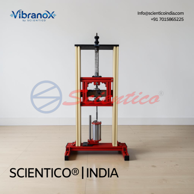
Spring Mass Vibration System | Vibrano X – 09
The Spring Mass Vibration System - Vibrano X - 09 is a bench top mounted unit to analyze the oscillations of a spring mass system. The sturdy bench top base secures two vertical guides in a vertical plane. This Spring Mass Vibration System supports both free and damped oscillation testing.
View product detailsAim of the Experiment
1. To determine the natural frequency of a spring-mass system under free vibration.
2. To study the effect of damping on free vibrations and determine the damping coefficient.
3. To study forced vibrations and observe the resonance condition.
Theory
Free Vibration, Undamped
A spring-mass system consists of a mass m attached to a spring of stiffness k. When displaced from its equilibrium position and released, the mass undergoes simple harmonic motion.
Equation of motion: mẍ + kx = 0
Natural frequency: fn = (1/2π)√(k/m) Hz
Natural circular frequency: ωn = √(k/m) rad/s
Time period: T = 2π√(m/k) seconds
Free Vibration, Damped
When damping is present (dashpot or viscous damping), the equation of motion becomes:
mẍ + cẋ + kx = 0
where c = damping coefficient (N·s/m)
Critical damping coefficient: cc = 2√(km) = 2mωn
Damping ratio: ζ = c/cc
For ζ < 1 (underdamped), the system oscillates with exponentially decaying amplitude:
x(t) = X·e^(-ζωnt)·cos(ωdt + φ)
Damped natural frequency: ωd = ωn√(1 – ζ²)
Logarithmic decrement: δ = ln(x₁/x₂) = 2πζ/√(1 – ζ²)
Forced Vibration and Resonance
When an external periodic force F(t) = F₀sin(ωt) is applied:
mẍ + cẋ + kx = F₀sin(ωt)
Amplitude at resonance (ω = ωn): X_res = F₀/(cωn)
Resonance: When the forcing frequency ω equals the natural frequency ωn, the amplitude reaches maximum. In undamped systems, amplitude theoretically becomes infinite at resonance.
Apparatus Required
- Spring-mass vibration apparatus (single degree of freedom, motorised exciter)
- Springs of different stiffness (k₁, k₂)
- Masses (disc weights) of known weight
- Dashpot assembly (for damped vibration)
- Stroboscope or optical tachometer
- Displacement sensor / dial gauge or LVDT
- Stopwatch
- Ruler
Procedure, Free Undamped Vibration
- Measure and record the stiffness k of the spring using a load-deflection test (apply known weights and measure deflection).
- Attach mass m₁ to the spring. Ensure the system is vertical and in equilibrium.
- Give the mass a small displacement (5–10 mm) and release it.
- Record the time for 10 complete oscillations using a stopwatch. Calculate the time period T and frequency fn.
- Compare with the theoretical value: fn_th = (1/2π)√(k/m).
- Repeat with masses m₂, m₃ (by adding disc weights). Plot fn vs. 1/√m.
Procedure, Damped Free Vibration
- Connect the dashpot to the mass-spring system.
- Give the system an initial displacement and release.
- Record successive amplitudes x₁, x₂, x₃ from the displacement trace or dial gauge.
- Calculate logarithmic decrement: δ = (1/n)ln(x₁/xₙ₊₁)
- Calculate damping ratio: ζ = δ/√(4π² + δ²)
- Change the dashpot oil to vary damping and repeat.
Procedure, Forced Vibration
- Connect the motorised eccentric exciter to the spring-mass system.
- Start the motor at the lowest speed setting.
- Gradually increase the motor speed in steps, measuring the amplitude at each step using the dial gauge or displacement sensor.
- Record the forcing frequency (from the stroboscope or tachometer) and corresponding amplitude.
- Note the speed at which maximum amplitude occurs, this is the resonance condition.
- Continue increasing speed beyond resonance and observe the decrease in amplitude.
- Plot the frequency response curve (amplitude vs. forcing frequency ratio ω/ωn).
Observation Tables
Table 1, Free Undamped Vibration
| Mass m (kg) | Time for 10 oscillations (s) | Period T (s) | fn_actual (Hz) | fn_theoretical (Hz) | % Error |
|---|---|---|---|---|---|
| m₁ = | |||||
| m₁+m₂ = | |||||
| m₁+m₂+m₃ = |
Table 2, Damped Free Vibration (Logarithmic Decrement)
| Amplitude x₁ (mm) | Amplitude x₂ (mm) | Amplitude x₃ (mm) | δ (log decrement) | ζ (damping ratio) |
|---|---|---|---|---|
Calculations
Spring stiffness from load-deflection: k = W/δ = mg/x (N/m)
Natural frequency: fn = (1/2π)√(k/m)
Logarithmic decrement: δ = ln(x₁/x₂)
Damping ratio: ζ = δ/√(4π² + δ²)
Damped natural frequency: fd = fn√(1 – ζ²)
Critical damping coefficient: cc = 2mωn = 2√(km)
Actual damping coefficient: c = ζ × cc
Results
- Natural frequency of the system = _____ Hz (actual) vs _____ Hz (theoretical)
- Damping ratio ζ = _____
- The resonance condition was observed at forcing frequency = _____ Hz
- At resonance, the amplitude was _____ mm (with damping = _____ Ns/m)
Viva Questions
- What is the difference between free vibration and forced vibration?
- Define resonance. Why is resonance dangerous in engineering structures?
- What is the effect of increasing damping on the resonant amplitude?
- Define degree of freedom. Give examples of 1-DOF and 2-DOF systems.
- What is logarithmic decrement and how is it used to find the damping ratio?
- What is the difference between overdamped, underdamped, and critically damped systems?
- How does adding mass affect the natural frequency of a spring-mass system?
Scientico India manufactures this and the full range of Theory of Machines equipment, model-specific and supplied to engineering colleges worldwide.
One honest ask
We don't gate anything on this site. You just read the whole thing free. If it was useful, leave your email and two things happen: we send you this page as a plain-text block you can paste into a tender file or an internal email, and we notify you the next time we publish a buyer tool like this one. Nothing else. No drip sequence, no sales calls booked without asking.