
About us
- HOME
- About us
Equipment mentioned in this guide
Review the product information, specifications and model before requesting a quotation.
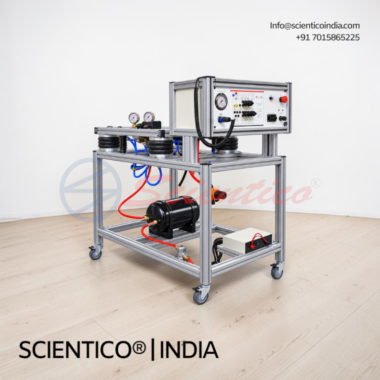
Air Suspension Trainer | SC-ASS 3015
Air Suspension Trainer SC-ASS 3015 is a hybrid PC-based and physical trainer for bus and truck air-suspension behaviour. All functional components used in the exercises are real, operating parts on a mobile steel frame.
View product details →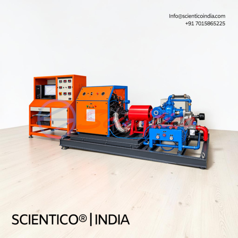
Diesel Engine Training Stand SC-DET 6025
The Diesel Engine Training Stand SC-DET 6025 is a fully functional 6-cylinder turbocharged common-rail diesel engine for demonstration and practical diagnosis. This diesel engine training stand includes a visible ECU, OBD-II access, and 12 switchable sensor and actuator faults.
View product details →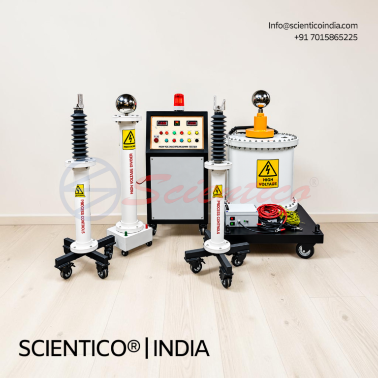
Portable High-Voltage Safety Tester | SC-HVT 2000
The Portable High-Voltage Safety Tester SC-HVT 2000 is a training instrument for checking hybrid and electric vehicle HV systems. It verifies absence of voltage, insulation resistance, and equipotential bonding without a vehicle. This portable high-voltage safety tester uses an HV demonstrator in the training case.
View product details →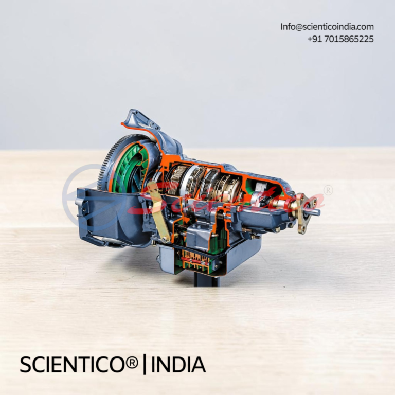
Sectioned Automatic Gearbox | SC-AGS 3011
The Sectioned Automatic Gearbox SC-AGS 3011 is a cut-away automatic gearbox for classroom demonstration and instruction. This sectioned automatic gearbox is mounted on a mobile stand, with all main assemblies opened so the class can follow the converter, clutches, and planetary sets.
View product details →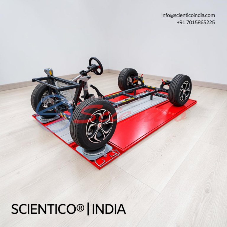
Wheel Alignment Training Stand | SC-WAS 3010
The Wheel Alignment Training Stand SC-WAS 3010 is an open training stand for demonstrating suspension geometry and practising wheel alignment. This wheel alignment training stand supports 3D aligners, CCD aligners, and mechanical methods, with measurement possible from all sides.
View product details →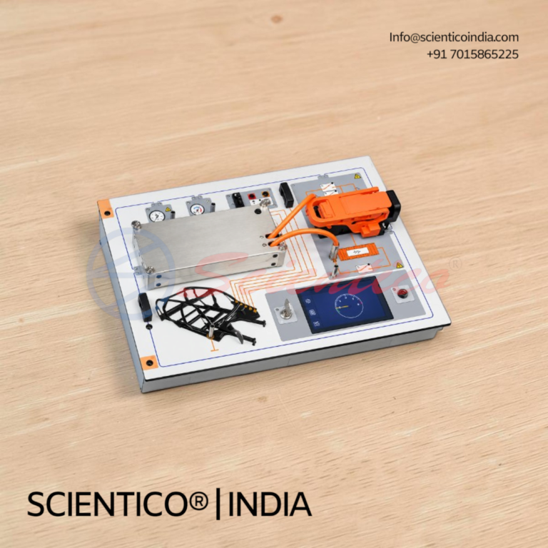
High-Voltage Electric Vehicle Safety Interactive Course | SC-HVS 2207
The High-Voltage Electric Vehicle Safety Interactive Course SC-HVS 2207 is a PC-based course for safe handling of high-voltage electric vehicles and charging systems. It includes course software, animations, an HV safety experiment unit, Class 0 safety gloves, and a Class 0 insulating mat.
View product details →About Scientico
Founded in 1993, SCIENTICO is a leading manufacturer and exporter of scientific, engineering, and laboratory equipment. With over three decades of experience, we design and deliver precision testing instruments and educational training systems for engineering colleges, universities, hospitals, and research laboratories worldwide.
Our in-house manufacturing, backed by ISO 9001:2015 certification and CE-marked products, ensures consistent quality, durability, and performance across all product categories.
- Over 30 years of manufacturing excellence in laboratory and engineering systems
- ISO 9001:2015 certified and CE-marked equipment for assured global compliance
- In-house research and design for continuous product innovation
- Export presence across 30+ countries with strong after-sales support

In-House Research & Development
Our dedicated R&D division continuously innovates to create cutting-edge laboratory and engineering equipment. Every product is developed and tested in-house to ensure precision, reliability, and long-term performance.
Certified Quality & Global Standards
SCIENTICO follows ISO 9001:2015 and CE compliance for all manufacturing processes. Each instrument undergoes rigorous quality checks to meet international benchmarks in accuracy, safety, and durability.
Worldwide Reach & Support
With exports across 30+ countries, we provide not only world-class products but also unmatched after-sales service and technical assistance. Our global presence ensures timely delivery and dependable customer support.
PRECISION MANUFACTURING EXCELLENCE
At SCIENTICO, manufacturing goes beyond production. It is built on decades of engineering expertise and hands-on experience.
Our facility in Ambala Cantt is equipped for machining, fabrication, and assembly, enabling us to deliver reliable laboratory and engineering equipment.
We manage the complete process in-house, from design and prototyping to final calibration, ensuring consistent performance, faster delivery, and dependable quality.
- Advanced Machining & Fabrication Capabilities
- Expert Technical Team
- In-House Production & Quality Control
our popular products
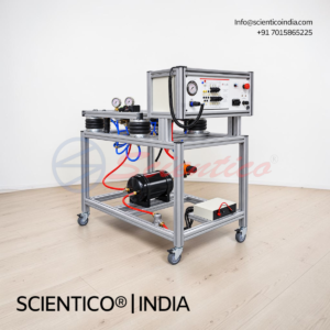
Air Suspension Trainer SC-ASS 3015 is a hybrid PC-based and physical trainer for bus and truck air-suspension behaviour. All functional components used in the exercises are real, operating parts on a mobile steel frame.
Product Overview
The Air Suspension Trainer SC-ASS 3015 simulates bus and truck air-suspension behaviour. It combines PC simulation with a physical trainer. Students work with real components, including air springs, valves, sensors, and a compressor. The unit supports ride-height, leak, valve, compressor, and sensor fault exercises.

The Diesel Engine Training Stand SC-DET 6025 is a fully functional 6-cylinder turbocharged common-rail diesel engine for demonstration and practical diagnosis. This diesel engine training stand includes a visible ECU, OBD-II access, and 12 switchable sensor and actuator faults.
Product Overview
The SC-DET 6025 diesel engine training stand uses a 6-cylinder in-line engine with 2.5 to 3.0 litre displacement, turbocharging, and Euro 4 emissions. It runs on diesel fuel available in Jordan. Common-rail injection, liquid cooling, and an oil sump with filter are fully functional. Air filter, intercooler, catalytic converter, and silencer are fitted. The outlet is prepared for workshop extraction through a 100 mm hose connection at approximately 600 m³/h. Sensors include MAP, MAF, ECT, CKP, CMP, IAT, O2, and knock. Actuators include injectors, throttle body, turbo actuator, and EGR valve. Twelve independently switchable faults support diagnostic training. The unit is CE compliant.
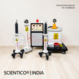
The Portable High-Voltage Safety Tester SC-HVT 2000 is a training instrument for checking hybrid and electric vehicle HV systems. It verifies absence of voltage, insulation resistance, and equipotential bonding without a vehicle. This portable high-voltage safety tester uses an HV demonstrator in the training case.
Product Overview
The SC-HVT 2000 portable high-voltage safety tester measures DC voltage from -1,000 V to +1,000 V and insulation resistance up to 1 GΩ. Insulation test voltage is selectable from 250 to 1,000 V DC in 16 steps. Equipotential bonding is measured with a four-wire method to UNECE R100, at test currents of 100 to 1,000 mA. Resistance ranges from 0 Ω to 10 MΩ, and a diode test provides polarity indication. Capacitance measurement is included. Menu-guided measurements are documented continuously, with values shown on a connected PC and test reports generated. The instrument is USB powered and supplied calibrated with a certificate.
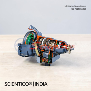
The Sectioned Automatic Gearbox SC-AGS 3011 is a cut-away automatic gearbox for classroom demonstration and instruction. This sectioned automatic gearbox is mounted on a mobile stand, with all main assemblies opened so the class can follow the converter, clutches, and planetary sets.
Product Overview
The SC-AGS 3011 sectioned automatic gearbox opens the housing, torque converter, converter lock-up clutch, oil pump, all clutches, all three planetary gear sets, and the hydraulic unit. Demonstrable functions include the converter, lock-up clutch, freewheels, oil pump, parking lock, clutches and planetary sets, and solenoid valves with the hydraulic unit. Cut surfaces are machined, deburred, painted in contrasting colours, and corrosion protected. The gearbox sits on a mobile stand with lockable castors and measures approximately 1,200 x 600 x 1,000 mm (W x D x H).
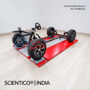
The Wheel Alignment Training Stand SC-WAS 3010 is an open training stand for demonstrating suspension geometry and practising wheel alignment. This wheel alignment training stand supports 3D aligners, CCD aligners, and mechanical methods, with measurement possible from all sides.
Product Overview
The SC-WAS 3010 wheel alignment training stand has an open construction that allows measurement from all sides without a lifting platform. Front suspension camber, SAI, and caster adjust through shock absorber position, eccentric bolts, and wheel position on the lower arm. Toe-in and toe-out adjust by tie rod. The rear multi-link suspension has three adjustment points for toe, camber, and wheelbase. Adjustment ranges cover camber ±3°, caster 0° to +8°, SAI 8° to 16°, and toe ±5 mm per wheel. Resolution is 0.05° and 0.5 mm. Measurable parameters include wheelbase, SAI, ride height, shear angle, turning radius, track width, and setback. The stand measures approximately 120 x 340 x 180 cm extended and weighs about 200 kg.
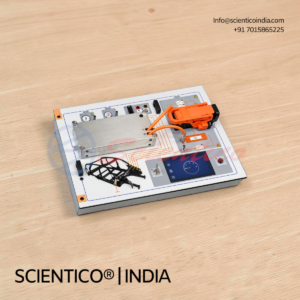
The High-Voltage Electric Vehicle Safety Interactive Course SC-HVS 2207 is a PC-based course for safe handling of high-voltage electric vehicles and charging systems. It includes course software, animations, an HV safety experiment unit, Class 0 safety gloves, and a Class 0 insulating mat.
Product Overview
The SC-HVS 2207 high-voltage electric vehicle safety course covers HV safety fundamentals, repair-shop job orders, and diagnostic functions. Students carry out measurement-based investigation and practical switchable fault exercises. The trainer operates only at safe extra-low voltage, 30 V DC and 12 V AC (SELV), so no live high voltage is present. The experiment unit demonstrates human-body resistance and electrical safety principles, with an earth-potential reference and resistance-measurement sockets. Class 0 gloves rated to 1,000 V AC are supplied with leather over-gloves in sizes 9 and 10. The insulating mat is IEC 61111 Class 0, 1000 x 1000 x 3 mm.
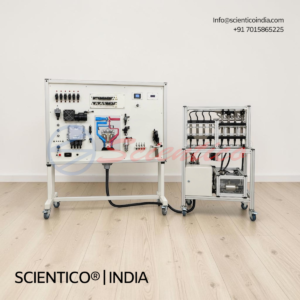
The Modern Common Rail Diesel Injection Interactive Course SC-CRD 2206 is a PC-based course on common rail diesel injection, pressures, procedures, and quantities. It includes course software, animations, and an experiment unit for common rail diesel injection.
Product Overview
The SC-CRD 2206 common rail diesel injection course covers diesel injection requirements and designs, common rail design and operation, and troubleshooting. It also covers injection response of solenoid and piezo injectors, low- and high-pressure circuits, electrical testing of injectors, and hydraulic components. Eight simulated faults support diagnostic and troubleshooting training. Experiments use virtual instruments on the interactive training interface SC-IPT 4016 or any functionally equivalent system.
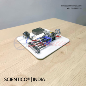
The Modern Vehicle Ignition Systems Interactive Course SC-IGN 2205 is a PC-based course for learning vehicle ignition systems. It includes application software, animations, and an experiment unit for pulse generation and ignition circuits.
Product Overview
The SC-IGN 2205 ignition systems course covers ignition spark generation, timing with mechanical and map control, and conventional and dual-spark ignition. It also covers transistorised ignition with Hall and inductive sensors, electronic ignition, and static and rotating high-voltage distribution. Students record and analyse ignition oscilloscope traces. Eight simulated faults support diagnostic and troubleshooting training. Experiments use software-based virtual instruments on the interactive training hardware or any functionally equivalent system.
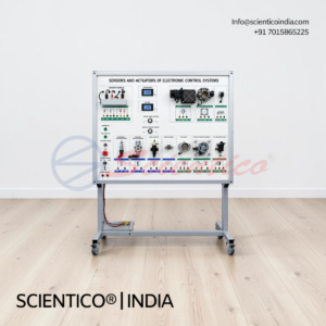
The Engine Management Sensors Interactive Course SC-ISM 2204 is a PC-based course for learning the operation, testing, and diagnosis of engine-management sensors. This engine management sensors course includes course software with animations, an experiment unit with pre-fabricated variable circuits, and virtual instrument practical work.
Product Overview
The SC-ISM 2204 engine management sensors course covers induction, Hall, and piezo effects, along with engine-control sensors. Topics include inductive and Hall speed sensors, throttle-position switches and potentiometers, hot-film and hot-wire MAF sensors, intake-manifold pressure, knock detection, and NTC and PTC temperature sensors. Eight relay-activated simulated faults support troubleshooting practice. Theory and practical work use virtual instruments on the interactive training interface SC-IPT 4016 or any functionally equivalent system. Software and documentation are in English, with Arabic available on request.
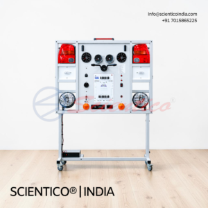
The Auxiliary Lamp Training Panel SC-ALP 1203 is a DIN A4 training panel with a 12 V, 55 W halogen lamp for auxiliary lighting experiments. This auxiliary lamp training panel fits the experiment unit supplied under this schedule and works with the interactive training hardware.
Product Overview
The SC-ALP 1203 auxiliary lamp training panel uses a 55 W H3 halogen lamp operating at 12 V. The lamp can be used as a fog lamp, searchlight, or other auxiliary light. Connections are made through 4 mm safety sockets on the panel. The panel is DIN A4 format and compatible with experiment unit Item 11008. The lamp housing is guarded, and the hot lens cannot be touched during training. The unit is CE compliant.
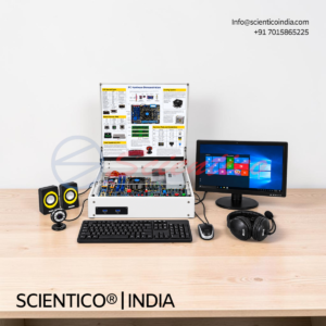
The Interactive Training Interface SC-IPT 4016 is a PC-connected unit for blended-learning experiments. It combines measurement, signal generation, power supply, and digital I/O in one bench housing. This interactive training interface is an open-architecture system that accepts interchangeable experiment cards and modules.
Product Overview
The SC-IPT 4016 interactive training interface uses a 32-bit ARM processor with internal memory for measurement data. It connects by USB 2.0 and WLAN 2.4 GHz (802.11 b/g/n), and supports multiple experiment modules at once. Four differential analogue inputs sample at 100 MSa/s with 10 MHz bandwidth. Two current inputs with 5 A overcurrent protection and three variable analogue outputs are included. Sixteen digital outputs, sixteen digital inputs, and eight relay outputs are provided. Virtual instruments include voltmeters, ammeters, a power meter, a multimeter, and 2- and 4-channel oscilloscopes at 10 MHz. Spectrum analysis and Bode plotting are included. Signal generation covers DC, function, arbitrary, and pulse sources. Power supply functions include three-phase and adjustable DC sources. Control software runs on Windows 10/11 (64-bit) under a perpetual site licence. PC and course software are separate items.
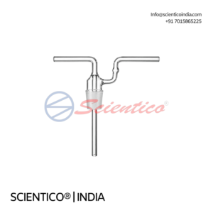
The Sintered Wash Bottle Head Laboratory Glassware GB 19 is a laboratory glass component for gas washing and filtration. This sintered wash bottle head supports efficient gas dispersion and is available in 125 ml and 250 ml.
Product Overview
The GB 19 sintered wash bottle head is made of laboratory-grade glass with excellent chemical resistance. The sintered construction disperses gas into fine bubbles for improved washing performance. The head fits compatible laboratory wash bottle systems. It is available in two capacities: 125 ml and 250 ml.
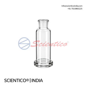
The Gas Washing Bottle with Interchangeable Joints GB 18 is a laboratory glass bottle for gas purification and absorption. This gas washing bottle features interchangeable joints for secure integration with laboratory gas handling systems and is available from 125 ml to 500 ml.
Product Overview
The GB 18 gas washing bottle is made of laboratory-grade glass with excellent chemical resistance. Interchangeable joints allow secure connection to laboratory gas handling systems. The bottle supports gas washing, purification, and absorption procedures. It is available in three capacities: 125, 250, and 500 ml.
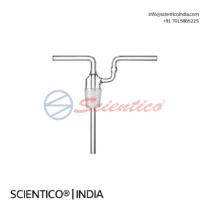
The Head for Gas Bottles GB 17 is a laboratory glass accessory for gas handling and collection. This gas bottle head provides secure fitting for compatible laboratory gas bottle systems and is available in 125 ml, 250 ml, and 500 ml.
Product Overview
The GB 17 gas bottle head is made of laboratory-grade glass with excellent chemical resistance. Its precision design supports secure fitting with compatible laboratory gas bottle systems. The head is available in three capacities: 125 ml, 250 ml, and 500 ml.
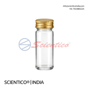
The Mac-Cartney Bottles with Aluminium Cap GB 16 are laboratory glass bottles for sample storage and chemical handling. These Mac-Cartney bottles feature an aluminium cap for secure sealing and are available from 15 ml to 60 ml.
Product Overview
The GB 16 Mac-Cartney bottle is made of laboratory-grade glass with excellent chemical resistance. The aluminium cap provides secure sealing for stored samples and chemicals. The compact structure supports convenient handling, storage, and transfer. The bottle is available in three capacities: 15, 30, and 60 ml.
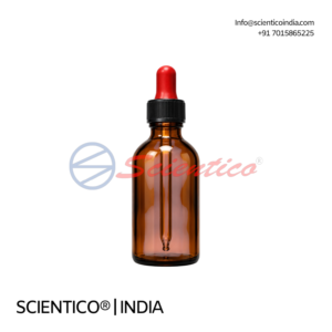
The Amber Dropping Bottle Neutral Hard Glass with Screw Cap and Rubber Teat GB 15 is an amber glass bottle for controlled dispensing of light-sensitive solutions. This amber dropping bottle features a screw cap and rubber teat and is available in 60 ml and 125 ml.
Product Overview
The GB 15 amber dropping bottle is made of neutral hard amber glass with excellent chemical resistance. The amber glass reduces light transmission, which helps protect photosensitive reagents. The screw cap provides secure sealing during storage and handling. The integrated rubber teat supports controlled, drop-wise dispensing. The bottle is available in two capacities: 60 ml and 125 ml.
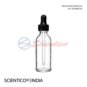
The Dropping Bottles Neutral Hard Glass with Screw Cap and Rubber Teat GB 14 are neutral glass bottles for controlled liquid dispensing. These dropping bottles feature a screw cap and rubber teat and are available in 60 ml and 125 ml.
Product Overview
The GB 14 dropping bottle is made of neutral hard glass with excellent chemical resistance. The screw cap provides secure sealing during storage and handling. The integrated rubber teat supports controlled, drop-wise dispensing. The bottle is available in two capacities: 60 ml and 125 ml.
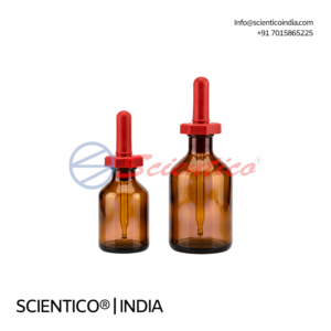
The Amber Glass Dropping Bottles with Rubber Teat GB 13 are Boro 3.3 amber glass bottles for controlled dispensing of light-sensitive solutions. These dropping bottles feature a ground in interchangeable stopper and are available from 30 ml to 250 ml.
Product Overview
The GB 13 dropping bottle is made of Boro 3.3 amber laboratory glass with excellent chemical resistance. The amber glass reduces light transmission, which helps preserve photosensitive reagents. The integrated rubber teat supports controlled, drop-wise dispensing. A ground in interchangeable stopper provides secure fitting and sealing. The bottle is available in four capacities: 30, 60, 125, and 250 ml.
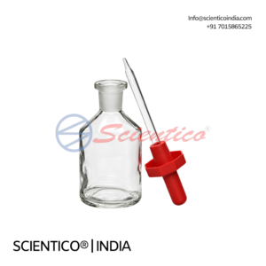
The Dropping Bottles with Ground In Interchangeable Stopper GB 12 are Boro 3.3 glass bottles for controlled liquid dispensing. These dropping bottles feature a rubber teat and a ground in interchangeable stopper, available from 30 ml to 250 ml.
Product Overview
The GB 12 dropping bottle is made of Boro 3.3 laboratory glass with excellent chemical resistance. The integrated rubber teat supports controlled, drop-wise dispensing. A ground in interchangeable stopper provides secure fitting and sealing. The bottle is available in four capacities: 30, 60, 125, and 250 ml.
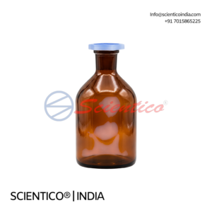
The Amber Glass Reagent Bottles with Interchangeable Stopper GB 11 are Boro 3.3 bottles for storing light-sensitive chemicals and samples. These amber glass reagent bottles feature an interchangeable stopper and are available from 30 ml to 2000 ml.
Product Overview
The GB 11 reagent bottle is made of Boro 3.3 amber laboratory glass with excellent chemical resistance. The amber glass reduces light transmission, which helps preserve photosensitive reagents. An interchangeable stopper provides secure sealing. The bottle is available in seven capacities: 30, 60, 125, 250, 500, 1000, and 2000 ml.
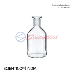
The Reagent Bottles Narrow Mouth with Plastic Stopper GB 10 are Boro 3.3 glass bottles for laboratory chemical storage and sample handling. These narrow mouth reagent bottles feature a plastic stopper for secure sealing and are available from 30 ml to 10000 ml.
Product Overview
The GB 10 narrow mouth reagent bottle is made of Boro 3.3 laboratory glass with excellent chemical resistance. The narrow mouth supports controlled pouring and reduces exposure to contaminants. A plastic stopper seals the bottle. The bottle is available in nine capacities: 30, 60, 125, 250, 500, 1000, 2000, 5000, and 10000 ml.
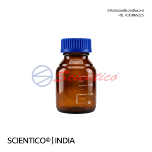
The Reagent Bottle with Screw Cap Amber Glass GB 09 is a laboratory glass bottle for storing light-sensitive chemicals and samples. This amber glass reagent bottle features a secure screw cap closure and is available from 10 ml to 10000 ml.
Product Overview
The GB 09 reagent bottle is made of laboratory-grade amber glass with excellent chemical resistance. The amber glass reduces light transmission, which supports storage of photosensitive reagents. The screw cap provides secure sealing against contamination. The bottle is available in 11 capacities from 10 ml to 10000 ml.
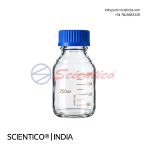
The Reagent Bottle with Screw Cap Clear Glass GB 08 is a laboratory glass bottle for chemical storage, sample handling, and analytical use. This clear glass reagent bottle features a secure screw cap closure and is available from 10 ml to 20000 ml.
Product Overview
The GB 08 reagent bottle is made of clear laboratory-grade glass with excellent chemical resistance. The screw cap provides secure sealing to protect stored chemicals and samples from contamination. The clear body allows the contents to be seen during handling. The bottle is available in 12 capacities from 10 ml to 20000 ml.
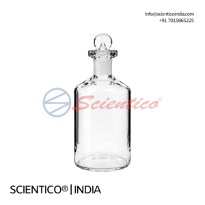
The B.O.D. Bottle with Interchangeable Stopper GB 07 is a laboratory glass bottle for biological oxygen demand testing and water analysis. This BOD bottle with interchangeable stopper provides secure sealing for sample handling.
Product Overview
The GB 07 B.O.D. bottle is made of laboratory-grade glass with excellent chemical resistance. The interchangeable stopper seals the bottle for reliable sample storage. The bottle is uncalibrated and suits water analysis and BOD testing. It is available in three capacities: 60 ml, 125 ml, and 300 ml.
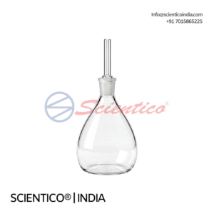
The Density Bottle Uncalibrated with Glass Capillary Stopper GB 06 is a laboratory glass bottle for density and specific gravity measurement. This uncalibrated density bottle with glass capillary stopper is available from 10 ml to 100 ml.
Product Overview
The GB 06 density bottle is made of laboratory-grade glass with excellent chemical resistance. A glass capillary stopper controls liquid displacement and limits excess liquid retention during measurement. The bottle is uncalibrated, so it suits general density determination and educational work. Capacities range from 10 ml to 100 ml in four variants: 10, 25, 50, and 100 ml.
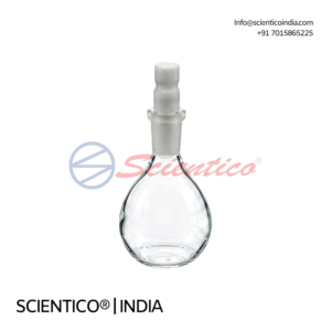
The Specific Gravity Bottle with Capillary Bore and Teflon Stopper GB 05 is a Class A laboratory glass bottle for accurate density and specific gravity measurement. This specific gravity bottle with capillary bore uses an interchangeable Teflon stopper for secure sealing.
Product Overview
The GB 05 specific gravity bottle is made of laboratory-grade glass with excellent chemical resistance. The capillary bore supports precise liquid displacement for density determination. An interchangeable Teflon stopper seals the bottle and reduces contamination. The bottle is manufactured as Class A laboratory glassware. Capacities range from 5 ml to 100 ml, with tolerances from ±0.1 ml to ±2.0 ml.
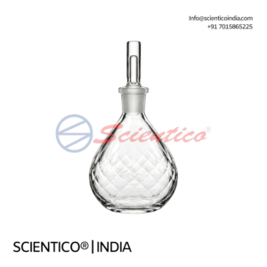
The Calibrated Density Bottle with Capillary Stopper GB 04 is a laboratory glass bottle for accurate density and specific gravity measurement. This calibrated density bottle with capillary stopper is supplied with an individual work certificate.
Product Overview
The GB 04 calibrated density bottle with capillary stopper is made of laboratory-grade glass with excellent chemical resistance. The calibrated design supports accurate volume measurement for density determination. The capillary stopper limits excess liquid retention and supports measurement consistency. Each bottle is supplied with an individual work certificate. Capacities range from 10 ml to 100 ml, with tolerances from ±1.0 ml to ±3.0 ml.
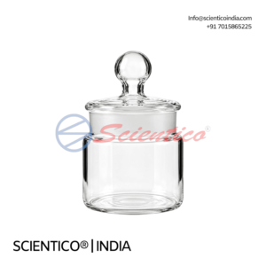
The Weighing Bottles with Ground In Stopper GB 03 are laboratory glass bottles for accurate weighing and sample storage. These weighing bottles feature a ground in stopper for secure sealing and are available in squat and tall forms.
Product Overview
The GB 03 weighing bottles are made of laboratory-grade glass with excellent chemical resistance. The ground in stopper seals the bottle and helps prevent contamination during weighing and storage. Squat and tall forms are available. Capacities range from 5 ml to 60 ml.
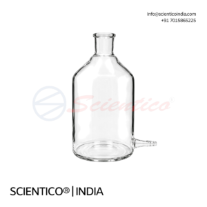
The Aspirator Bottle with Outlet for Tubing GB 02 is a laboratory glass bottle for liquid storage, filtration, and transfer. This aspirator bottle with tubing outlet provides a secure connection for laboratory tubing.
Product Overview
The GB 02 aspirator bottle is made of laboratory-grade glass with excellent chemical resistance. An integrated outlet accepts laboratory tubing for controlled liquid transfer. The bottle is available in five capacities from 100 ml to 2000 ml.

The Aspirator Bottle with Grounded Neck and Side Socket Bottom GB 01 is a laboratory glass bottle for liquid storage, filtration, and transfer. This aspirator bottle with grounded neck has a side socket bottom for controlled discharge.
Product Overview
The GB 01 aspirator bottle is made of laboratory-grade glass with excellent chemical resistance. The grounded neck provides a secure fit with compatible laboratory apparatus. A side socket at the bottom supports controlled liquid discharge. The bottle is available in four capacities from 2000 ml to 20000 ml, with side socket sizes from 24/29 to 34/35.

The Conical Philips Beaker with Pour Spout GLB 08 is a borosilicate beaker for mixing, decanting, and liquid handling. This conical Philips beaker with pour spout has a narrower mouth than its base for better liquid control.
Product Overview
The GLB 08 conical Philips beaker with pour spout is made of borosilicate glass. Its conical (Philips) design has a narrower mouth than the base, which supports controlled mixing and decanting. The integrated pour spout allows accurate transfer. The beaker is available in 250 ml and 500 ml. Approximate sizes are 68 x 110 mm for 250 ml and 88 x 145 mm for 500 ml.

The Laboratory Tall Form Beaker with Pour Spout GLB 07 is a borosilicate beaker for heating, mixing, and liquid handling. This tall form beaker with pour spout has clear graduations and a durable marking area.
Product Overview
The GLB 07 tall form beaker with pour spout is made of borosilicate glass. Its tall design uses limited bench space efficiently. The integrated pour spout allows smooth, controlled transfer. Uniform wall thickness supports even heating. Clear graduations support volume reference. A durable marking area aids identification. The beaker is available in 8 capacities from 50 ml to 1000 ml.

The Laboratory Tall Form Beaker without Spout GLB 06 is a borosilicate beaker for heating and mixing applications. This tall form beaker without spout offers clear graduations and a large labelling area.
Product Overview
The GLB 06 tall form beaker without spout is made of borosilicate glass. Its tall design makes efficient use of bench space. The beaker has no spout, which supports controlled handling. Uniform wall thickness supports even heating. Clear graduations support volume reference. A large labelling area aids identification. The beaker is available in 8 capacities from 50 ml to 1000 ml.

The Tablet Disintegration Beaker GLB 05 is a 1000 ml borosilicate beaker for tablet disintegration testing. This tablet disintegration beaker features a large labelling area and is designed for use with disintegration testing machines.
Product Overview
The GLB 05 tablet disintegration beaker is made of borosilicate glass with a capacity of 1000 ml. Approximate size is 105 x 145 mm. A large labelling area allows easy marking and identification during testing. The beaker is designed for compatibility with tablet disintegration testing machines and offers chemical resistance and durability.
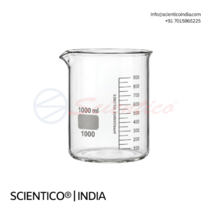
The Laboratory Griffin Beaker Low Form with Pour Spout GLB 04 is a borosilicate beaker for liquid handling, mixing, and heating. This griffin beaker low form has clear graduations and an integrated pour spout.
Product Overview
The GLB 04 griffin beaker low form is made of borosilicate glass with a low form (Griffin) design for stability. The integrated pour spout allows precise pouring. Uniform wall thickness supports even heating. Clear graduations support measurement from 25 ml upward. A large labelling area aids identification. The beaker is available in 16 capacities from 5 ml to 10000 ml.
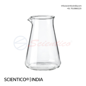
The Conical Glass Beaker with Spout and Graduation GLB 03 is a borosilicate laboratory beaker for liquid handling, mixing, and testing. This conical glass beaker with spout and graduation has printed volume markings and an integrated pouring spout.
Product Overview
The GLB 03 conical glass beaker with spout and graduation is made of borosilicate 3.3 glass with a clear, transparent body. Its conical body supports controlled mixing and liquid movement. Printed graduations support volume reference. The integrated spout allows smooth pouring with reduced spillage. The beaker suits chemical handling and heating. It is available in 2 capacities: 250 ml and 500 ml.
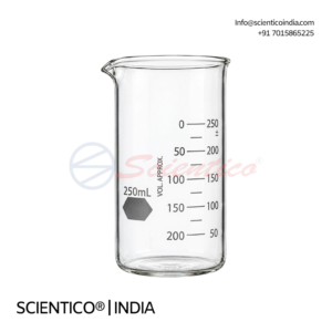
The Tall Form Glass Beaker with Graduation glb-02 is a borosilicate laboratory beaker for liquid handling, mixing, and heating. This tall form glass beaker with graduation has printed volume markings and an integrated pouring spout.
Product Overview
The glb-02 tall form glass beaker with graduation is made of borosilicate 3.3 glass with a clear, transparent body. Its tall form reduces splashing during stirring and heating. Printed graduations support volume reference. The integrated spout allows controlled pouring. The beaker suits chemical handling and heating. It is available in 10 capacities from 25 ml to 1000 ml. The glass has a smooth internal and external surface for cleaning.
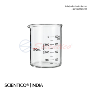
The Low Form Glass Beaker with Graduation GLB 01 is a borosilicate laboratory beaker for measuring, mixing, heating, and solution preparation. This low form beaker with graduation has a printed volume scale and an integrated pouring spout.
Product Overview
The GLB 01 low form beaker with graduation is made of borosilicate 3.3 glass with a clear, transparent body. Its low form structure gives stability during mixing and stirring. A printed graduation scale supports volume reference. The integrated spout allows controlled pouring. The beaker suits heating and chemical handling. It is available in 16 capacities from 5 ml to 10000 ml. The glass is designed for thermal shock resistance and a smooth internal surface for cleaning.

The Combustion Laboratory Unit ThermoFlux 12099 is a frame-mounted training system for studying combustion and commercial gas and oil burners. This combustion laboratory unit includes a fitted gas burner, a separate oil burner, and full instrumentation for supervised student operation.
Product Overview
The ThermoFlux 12099 combustion laboratory unit studies burner firing rate, turndown range, flame stability, flame shape, and flame radiation. A stainless steel, water-cooled combustion chamber has four 100 mm quartz windows. The gas burner is fitted as standard and runs on natural gas or LPG at up to approximately 100 kW. The oil burner uses pressure jet atomisation with 1.5 and 2.2 US gal/hr interchangeable nozzles, up to approximately 108 kW. A handheld gas analyser measures flue gas O₂ for air-fuel ratio and combustion efficiency.
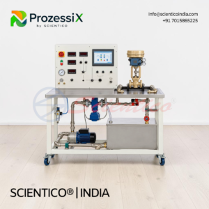
The Test Stand for Control Valves Prozessi PX-32 is a water-circuit trainer for testing and characterizing control valves. This control valve test stand determines Kv and Kvs values and plots valve characteristics using step-response analysis.
Product Overview
The PX-32 control valve test stand uses a 90 L water tank and a two-stage centrifugal pump with 22 m maximum head and 5.4 m³/h maximum flow. A gate valve sets flow, which an electromagnetic sensor measures from 0 to 4500 L/h. Two 0 to 6 bar pressure sensors measure pressure upstream and downstream of the valve. Electro-pneumatic valves are actuated by potentiometer with 4 to 20 mA signal and supplied air at 0 to 6 bar. Motorised valves are operated by pushbuttons. Position feedback uses current or resistance signals. USB data acquisition runs on Windows.
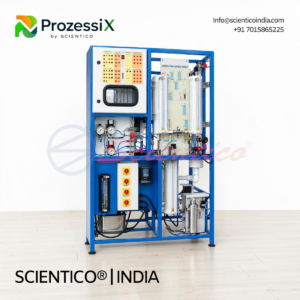
The Universal Process Control Trainer Prozessi PX 29B is a modular process control training system for PLC programming, SCADA, process instrumentation, and marine engineering process control. This universal process control trainer uses a Honeywell HC900 process controller and integrates temperature, flow, level, and pressure processes.
Product Overview
The PX 29B universal process control trainer covers manual and automatic control, single-loop and multi-loop control, cascade, feedforward, ratio, and MIMO control. A Honeywell HC900 process controller and a Honeywell ControlEdge PLC support Ladder Logic and Function Block Diagram programming. Marine cooling-water, tank-level, pump sequencing, and pressure alarm experiments are included. A 3 kW heating tank, centrifugal pump, and VFD-driven diaphragm pump supply process fluid. Pneumatic control valves with I/P converters regulate flow. Integrated SCADA provides monitoring, trending, and data export.
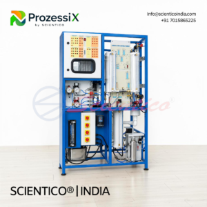
The Universal Process Control Trainer Prozessi PX 29A is a modular industrial process control training system for PLC programming, SCADA, process instrumentation, and advanced process control. This universal process control trainer integrates temperature, flow, level, and pressure processes on one platform.
Product Overview
The PX 29A universal process control trainer studies manual and automatic control, single-loop and multi-loop control, cascade, feedforward, ratio, and MIMO control. Temperature, flow, level, and pressure processes run on one workbench. A 3 kW heating tank, centrifugal pump, and VFD-driven diaphragm pump supply process fluid. Pneumatic control valves with I/P converters and electronic positioners regulate flow. PLC-based control and integrated SCADA supervise the process. Over 25 configurable experimental setups are available.
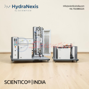
The Depth Filtration Unit HydraNexis HNX 09A is a rapid sand filtration trainer for water and wastewater treatment studies. This depth filtration unit features a transparent filter column, multi-tube manometer, and quartz sand filter media.
Product Overview
The HNX 09A depth filtration unit studies rapid sand filtration in gravity-flow and pressurised modes up to 1 bar. The transparent, shatter-resistant column measures at least 100 mm internal diameter and 1200 mm height. Filter bed height is adjustable up to 800 mm, using quartz sand of 0.5 to 1 mm particle size. A minimum of 10 sampling ports sit along the bed, with a minimum 10-tube manometer for pressure distribution. A raw water pump with corrosion-resistant impeller feeds a storage tank of at least 150 litres. Outlet control valves and a flow meter support flow studies. Backwashing regenerates the filter bed.
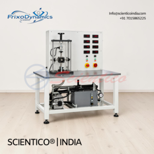
The Journal Bearing with Hydrodynamic Lubrication Machine FX 536 is a trainer for studying friction in hydrodynamically lubricated radial journal bearings. This journal bearing hydrodynamic lubrication machine varies bearing clearance, radial load, and shaft speed while measuring friction and shaft position.
Product Overview
The FX 536 journal bearing hydrodynamic lubrication machine uses shafts of different diameters to vary bearing clearance. Radial load is applied by handwheel and compression spring, then measured electronically. A lever arm with force sensor measures frictional moment. A three-phase motor with frequency converter drives the shaft from 0 to 1600 rpm. A hydraulic unit controls oil temperature. Inductive sensors measure shaft position at four points in the X and Y directions to plot shaft locus. Software supports USB data acquisition on Windows 11.
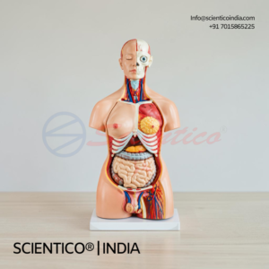
The 85 cm Unisex Torso 40 Parts NL 03 is a detailed anatomy model for teaching thoracic and abdominal structures. This unisex torso model includes removable female breast plate, brain, lung, heart, liver, kidney, and reproductive organ components.
Product Overview
The NL 03 unisex torso is an 85 cm model built from 40 parts. It includes a female breast plate, head, eyeball, and brain in eight parts. Vertebrae with spinal nerves are shown in four parts. Lungs come in four parts and the heart in two. The trachea, esophagus, descending aorta, and diaphragm are included. The liver, kidney, and stomach (two parts) are modelled. Intestines are provided in four parts. Male genitalia are shown in four parts, and female genitalia with fetus in three parts.
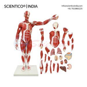
The Muscular Human Body 78 cm 27 Parts NL 102 is a PVC anatomy model with removable organs for teaching human anatomy. This muscular human body 78 cm model includes brain, lung, heart, liver, intestine, and stomach components.
Product Overview
The NL 102 muscular human body 78 cm model is made of PVC. Removable organs include the brain (2 parts), lungs (2 parts), heart (2 parts), liver, intestines, and stomach. Feature markings cover the head and neck, body wall, thoracic viscera, abdominal and pelvic viscera, upper limb, and lower limb regions. The model mounts on a stand with base.
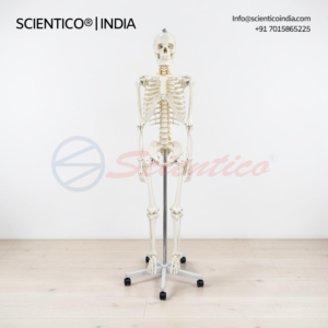
The Human Skeleton Male Life Size Articulated NL 98 is a life-size PVC anatomy model for teaching skeletal structure. This human skeleton male life size articulated model features a removable bonnet, movable mandible, and separately mounted coccyx.
Product Overview
The NL 98 human skeleton male life size articulated model is made of PVC and sized to life scale. The bonnet removes to show the interior of the skull. The mandible moves, and the teeth are fitted separately. Skull foramina, fissures, and processes are clearly depicted. The model shows the cervical artery, nerves, a prolapsed (herniated) disk, and the hyoid bone. The coccyx mounts separately, and the sacral canal is clearly depicted. Upper and lower limbs detach easily. The model is washable and unbreakable. It mounts on a stand with rollers.
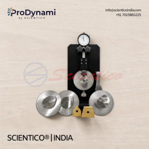
The Cam & Follower Apparatus ProDynami 1256 is a simple experimental set-up for studying cam mechanisms and their displacement curves. This cam and follower apparatus includes four interchangeable cams and three follower types for classroom demonstration.
Product Overview
The ProDynami 1256 cam and follower apparatus demonstrates the action principle of cam mechanisms. Four cams are supplied: arc, tangent, concave, and asymmetric. The follower operates as a roller tappet, cup tappet, or trailing lever. A mechanical dial gauge measures stroke from 0 to 20 mm with 0.01 mm graduations. An angled scale reads rotation from 0 to 360° with 1° graduations. The scale disk is 100 mm in diameter. Cams and tappets change without tools.
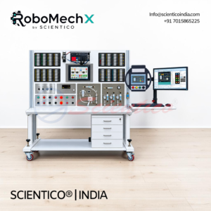
The PLC and HMI Advanced Training System MX-07 is a hands-on trainer for industrial automation, PLC programming, and HMI operation. This PLC and HMI advanced training system is built around a Siemens SIMATIC S7-1500 PLC with CPU 1511-1 PN and a 10.1-inch MTP1000 Unified HMI.
Product Overview
The MX-07 PLC and HMI advanced training system uses a Siemens SIMATIC S7-1500 PLC with CPU 1511-1 PN. A 10.1-inch Siemens MTP1000 Unified HMI supports process monitoring and control. STEP 7 Professional V21, WinCC Unified Engineering V21, and S7-PLCSIM support programming, HMI configuration, and simulation. Digital and analog inputs and outputs connect sensors and actuators through labelled safety sockets. An industrial Ethernet switch links the PLC, HMI, and engineering PC. Thirteen dynamic and six static automation modules cover motor control, sensing, pneumatics, and process applications.

The Hydraulic Training System (Basic Level) MX-04 is a hands-on trainer for hydraulic components, fluid power principles, and actuator operation. This hydraulic training system basic level uses a vertical profile plate with a 10/40 L power pack, cylinders, valves, and a hydraulic motor.
Product Overview
The MX-04 hydraulic training system basic level mounts on a modular vertical profile plate. A 10/40 L power pack with oil drives a double acting cylinder and hydraulic motor. Directional control uses 4/2-way and 4/3-way hand lever valves. Two-way and one-way flow control valves regulate flow. Three 100 kg/cm² pressure gauges, a pressure relief valve, and non-return valves support pressure control. A measuring scale and weight unit allow cylinder movement and load studies.
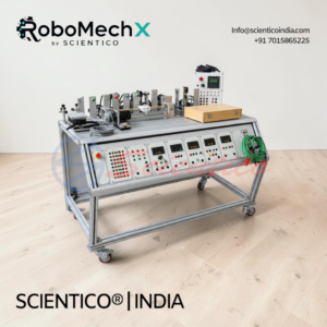
The Sensor Trainer Kit RoboMechX 12 is a practical trainer for industrial sensor technology, object detection, and sensor signal evaluation. This sensor trainer kit includes magnetic, inductive, capacitive, optical, fibre optic, colour, and ultrasonic sensors on a modular inclined profile plate.
Product Overview
The RoboMechX 12 sensor trainer kit mounts on a modular educational inclined profile plate. It includes magnetic, inductive, capacitive, optical, fibre optic, colour, and ultrasonic sensors. Sensor-specific workpieces support material detection exercises. A linear motion guide unit positions sensors during trials. A relay logic unit and electrical push button module support switching exercises. A 24 V DC, 4 A SMPS powers the system. A digital multimeter takes electrical readings.

The Pneumatics Training System (Advanced Level) MX-02A is a hands-on trainer for pneumatic control, circuit design, logic control, and sequencing. This pneumatics training system advanced level includes an inclined profile plate, FRL unit, cylinders, directional valves, and pneumatic logic components.
Product Overview
The MX-02A pneumatics training system advanced level runs on a modular inclined profile plate. It includes an FRL unit with pressure gauge, single acting and double acting cylinders, and a range of 3/2-way, 5/2-way, and 5/3-way valves. Pneumatic logic includes shuttle (OR) and dual pressure (AND) valves. Pressure sequence, back pressure, and time-delay valves support pressure, time, and position-dependent control. A pneumatic counter and proximity switch add sequencing capability. Tubing, fittings, a tube cutter, an air compressor, and textbooks are supplied.

The Electro-Hydraulic Training System MX-05 is a hands-on trainer for learning how electrical and hydraulic control systems work together. This electro-hydraulic training system covers solenoid valves, relays, limit switches, and basic to advanced circuit design.
Product Overview
The MX-05 electro-hydraulic training system is a sturdy, self-explanatory trainer on a frame with caster wheels. It includes a power unit, cylinders, a hydraulic motor, valves, pressure gauges, and an accumulator. Electrical modules include push buttons, relays, a digital time relay, limit switches, and inductive, capacitive, and optical sensors. Inbuilt safety measures and leakage protection are provided. Optional simulation software supports circuit design and troubleshooting.
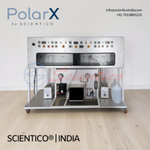
The Air Conditioning Test Rig (Duct Type) PolarX 556A is a 1 TR duct-type trainer for studying air conditioning and refrigeration processes. This air conditioning test rig covers cooling, heating, and steam humidification.
Product Overview
The PolarX 556A air conditioning test rig combines a 1 TR refrigeration circuit with a duct-type air conditioning section. Cooling, heating, and humidification experiments are possible on one rig. A steam generator and steam injector provide humidification. Six PT-100 sensors measure air and refrigerant conditions. Pressure, refrigerant flow, air velocity, voltage, current, and energy are all measured. High-pressure and low-pressure cutouts protect the refrigeration circuit.
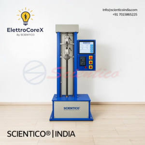
properties of materials under tensile load. This tensile tester kit includes a pre-assembled tensile tester, aluminium, steel, and PVC specimens, and a dial caliper for extension measurement.
Product Overview
The FortiTestX 54 tensile tester kit includes a pre-assembled tensile tester, one aluminium specimen, one steel specimen, and one PVC specimen. A dial caliper measures extension. A hex tool supports adjustments. A printed manual gives step-by-step procedures. A storage case keeps components organized. The kit supports tests to fracture, tensile strength determination, and force-extension plotting.

The Incremental Position Encoder EL 2045 is a laboratory encoder for position and speed measurement. It provides 1024 pulses per revolution, a 0.3 kW rating, and a maximum speed of 6000 rpm.
Product Overview
The EL 2045 incremental position encoder outputs 1024 pulses per revolution. It is rated 0.3 kW and operates up to 6000 rpm. The unit has two shaft ends.
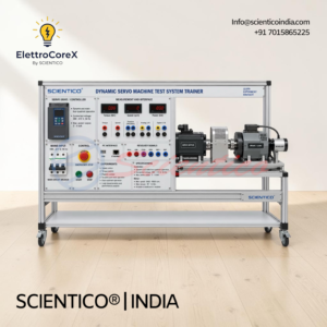
The Dynamic Servo Machine Test System Trainer EL 2041 is a laboratory system for testing servo machines under dynamic and static four-quadrant operation. It pairs a controller rated 3 to 5 kVA with a servo motor that includes a brake and resolver.
Product Overview
The EL 2041 dynamic servo machine test system trainer uses a controller that supports dynamic and static four-quadrant operation. The controller runs from a 380 to 415 V, 50 Hz supply and delivers 3 to 5 kVA maximum power output. The servo motor reaches 3000 to 6000 rpm with 10 to 15 Nm maximum torque. A brake and a resolver are included with the motor.
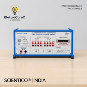
The Adapter for Power Electronics and Process Control Trainer EL 2039 is a separate hardware interface for connecting power electronics and process control trainers to a computer. It provides a USB programming adapter with galvanic isolation and supports hardware-in-the-loop operation.
Product Overview
The EL 2039 adapter for power electronics and process control trainer is a separate hardware interface. It includes a programming adapter with USB port. Galvanic isolation protects the computer and the trainer. Hardware-in-the-loop support enables real-time interaction between the trainer and simulation software.

The Power Electronics Converter Trainer EL 2036 is a laboratory unit with a three-phase, two-level IGBT converter for power electronics experiments. It provides 1 to 2 kVA output power from a 380 to 415 V, 50 Hz three-phase supply.
Product Overview
The EL 2036 power electronics converter trainer uses a three-phase, two-level IGBT converter with integrated brake chopper and control unit. A measurement unit records 3 currents and 6 voltages. A PC interface supports data handling. Output power ranges from 1 to 2 kVA. The unit operates from a 380 to 415 V, 50 Hz three-phase supply.

The Stabilized High Voltage DC Supply Trainer EL 2025 is a laboratory power supply with 0 to 500 V DC output. It delivers up to 6 A DC with 0.1% control accuracy and overvoltage, overcurrent, and overtemperature protection.
Product Overview
The EL 2025 stabilized high voltage DC supply trainer provides 0 to 500 V DC output at 0 to 6 A DC. Power rating is 1000 to 2000 W. Control accuracy is 0.1%. Overvoltage, overcurrent, and overtemperature protection safeguard the unit and connected circuits.

The Three-Phase Power Supply Trainer EL 2023 is a laboratory power supply unit providing three-phase outputs with neutral. It includes a motor protection switch with adjustable current, under-voltage trip, and safety cut-out.
Product Overview
The EL 2023 three-phase power supply trainer provides outputs L1, L2, L3, and N. A motor protection switch with adjustable current protects connected loads. An under-voltage trip and safety cut-out add protection for operators and equipment.

The Rheostat Trainer EL 1028 is a laboratory unit with variable and fixed resistive loads for electrical experiments. It includes a 0 to 1000 ohm, 500 W adjustable rheostat, a 1000 ohm, 180 W resistor, and a 0 to 2200 ohm, 20 W rheostat.
Product Overview
The EL 1028 rheostat trainer includes a 0 to 1000 ohm adjustable rheostat rated 500 W. A fixed 1000 ohm resistor rated 180 W is included. A second adjustable rheostat ranges from 0 to 2200 ohm and is rated 20 W.

The Regulating Transformer and Rectifier Trainer EL 1026 is a laboratory unit providing adjustable AC and DC output for electrical experiments. It offers 0 to 200 V at 2 A and 0 to 30 V at 10 A, both AC and DC, from a 220 to 250 V, 50 Hz supply.
Product Overview
The EL 1026 regulating transformer and rectifier trainer delivers 0 to 200 V output at 2 A in AC or DC. A second output provides 0 to 30 V at 10 A in AC or DC. The unit operates from a 220 to 250 V, 50 Hz supply.
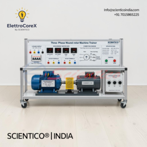
The Three-Phase Wound-Rotor Machine Trainer EL 1024 is a laboratory unit for studying wound-rotor machine operation. It is rated 400/230 V, 50 Hz, 0.87/1.5 A nominal current, 1400 to 3000 rpm nominal speed, and 0.25 to 1 kW nominal power.
Product Overview
The EL 1024 three-phase wound-rotor machine trainer operates at 400/230 V, 50 Hz nominal voltage. Nominal current is 0.87 A at 400 V and 1.5 A at 230 V. Nominal speed ranges from 1400 to 3000 rpm. Nominal power ranges from 0.25 to 1 kW.
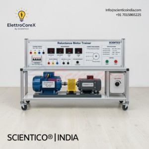
The Reluctance Motor Trainer EL 1022 is a laboratory unit for studying reluctance motor operation. It is rated 400/230 V, 50 Hz, 1.4/2.4 A nominal current, 1500 to 3000 rpm nominal speed, and 0.25 to 1 kW nominal power.
Product Overview
The EL 1022 reluctance motor trainer operates at 400/230 V, 50 Hz nominal voltage. Nominal current is 1.4 A at 400 V and 2.4 A at 230 V. Nominal speed ranges from 1500 to 3000 rpm. Nominal power ranges from 0.25 to 1 kW.

The DC Compound Wound Machine Trainer EL 1020 is a laboratory unit for studying DC compound wound machine operation. It is rated 200 to 300 V nominal voltage, 1.3 to 3 A nominal current, 2000 to 3000 rpm nominal speed, and 0.2 to 1 kW nominal power.
Product Overview
The EL 1020 DC compound wound machine trainer operates at 200 to 300 V nominal voltage and 1.3 to 3 A nominal current. Nominal speed ranges from 2000 to 3000 rpm. Nominal power ranges from 0.2 to 1 kW.
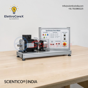
The Synchronous Servo Motor Trainer EL 1018 is a laboratory unit for studying synchronous servo motor operation. It is rated 300 to 400 V nominal voltage, 2.5 to 5 A nominal current, 3000 to 6000 rpm nominal speed, and 0.6 to 1 kW nominal power.
Product Overview
The EL 1018 synchronous servo motor trainer operates at 300 to 400 V nominal voltage and 2.5 to 5 A nominal current. Nominal speed ranges from 3000 to 6000 rpm. Nominal power ranges from 0.6 to 1 kW.

transformer operation. It accepts 380 to 415 V, 50 Hz three-phase input and provides two output voltage options.
Product Overview
The EL 1014 three-phase transformer trainer accepts 380 to 415 V three-phase, 50 Hz input. Output 1 provides 50 to 150 V three-phase with center tap. Output 2 provides 380 to 415 V three-phase. Power rating is 300 to 500 VA. Protection circuit breakers include under-voltage trip.

The Power Electronics Load Trainer EL 1016 is a load module for power electronics experiments. It provides three resistive loads and three inductive loads for circuit testing.
Product Overview
The EL 1016 power electronics load trainer includes three resistors, each rated 300 to 600 ohms and 100 to 200 W. It also includes three inductors, each rated 0.1 to 0.2 H and 0.5 to 1 A. The loads support power electronics circuit experiments requiring resistive and inductive loading.
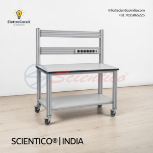
The Mobile Experiment Stand EL 1012 is a mobile frame for mounting laboratory experiments and equipment. This mobile experiment stand includes a table top, a shelf, and a power strip with six outlet sockets.
Product Overview
The EL 1012 mobile experiment stand has a table top and a shelf, with the shelf at least 30 mm thick. The frame uses two extruded aluminium profiles with multiple grooves for standard industrial mountings. Four H-shaped aluminium profiles complete the frame. A power strip with six outlet sockets supplies the mounted equipment.

The Hydraulic Bench (Gravimetric) FluidoSugreX 103 is a basic module for fluid mechanics experiments. This gravimetric hydraulic bench uses a closed water circuit and a gravimetric flow rate measurement system.
Product Overview
The FluidoSugreX 103 gravimetric hydraulic bench has a flow channel for weir experiments. A collecting tank and measuring tank provide gravimetric flow measurement. Measuring tank weight is read by a lever arm mechanism or optional digital load cells. The supply tank includes a centrifugal pump. The closed circuit does not need an external water supply.
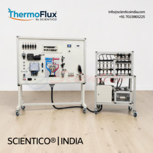
The Diesel Engine Control System CR/EDC 15 Educational Trainer ThermoFlux 2930 is a training board-simulator for common rail diesel injection and engine control. This diesel engine control system educational trainer integrates Bosch EDC 15C3-4.1 with OEM components in a mobile aluminum frame.
Product Overview
The ThermoFlux 2930 diesel engine control system educational trainer uses OEM components and the Bosch EDC 15C3-4.1 engine control system. It illustrates the operation modes of direct fuel injection. The electronic board measures 1820 x 1360 x 500 mm. The mechanical trolley measures 1500 x 800 x 500 mm. The unit weighs approximately 135 kg. It runs on 220/12 V power, with 110 V US supply available.
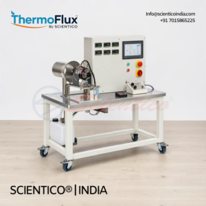
The Gas Turbine Jet Engine Test Bench ThermoFlux 7086A is an experimental system for studying the operating behaviour of a small single-shaft jet engine. This gas turbine jet engine test bench includes integrated thrust measurement and supports specific thrust, specific fuel consumption, and lambda analysis.
Product Overview
The ThermoFlux 7086A gas turbine jet engine test bench uses a single-shaft engine with radial compressor and axial turbine. Maximum thrust is 80 N at 120,000 min⁻¹. The turbine sits on a moving base with a force sensor for thrust measurement. An electric starter enables fully automatic start-up. A protective grating guards the engine. A remote control unit displays and controls engine operation. The system runs on kerosene or petroleum with turbine oil from a 5 L fuel tank. Measurements cover differential pressure, combustion chamber pressure, temperature, speed, fuel consumption, and force.
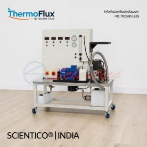
The Test Stand for Single Cylinder 7.5kW Engine ThermoFlux 2927 is a control and load unit for measuring power output of single-cylinder internal combustion engines. This test stand for single cylinder 7.5kW engine uses an air-cooled asynchronous brake motor with energy recovery for two-stroke and four-stroke petrol engines.
Product Overview
The ThermoFlux 2927 test stand for single cylinder 7.5kW engine delivers up to 7.5 kW braking power through an air-cooled asynchronous motor with energy recovery unit. A frequency converter generates torque and speed. Braking energy feeds back into the system for efficient operation. Torque is measured by a suspended brake unit and force sensor. Elastic claw coupling transmits force from engine to brake. A vibration-insulated base plate supports engine mounting. A stabilization tank smooths intake air. Potentiometers adjust braking torque and speed continuously. The stand measures torque, air temperature, intake air quantity, intake pressure, speed, fuel consumption, and fuel temperature. Exhaust gas and cooling water temperatures are displayed. Software supports USB data acquisition on Windows.
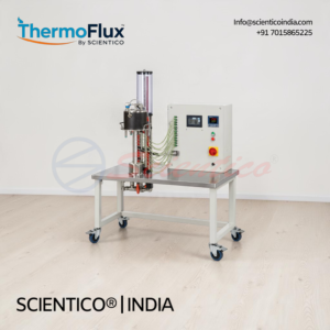
The Steady State and Non-Steady State Heat Conduction Test Bench ThermoFlux 2923 is a practical trainer for studying heat transfer through solid materials. This heat conduction test bench covers steady-state and transient conduction in five metals and supports thermal conductivity calculation.
Product Overview
The ThermoFlux 2923 heat conduction test bench investigates steady and transient heat conduction in metal samples. Five metals are supplied as 40 mm diameter bars: copper, aluminium, and brass at 450 mm, and steel and stainless steel at 300 mm. An electronically regulated heating water circuit with 800 W PID-controlled heater supplies heat at 20 to 85°C. An elevated tank with overflow provides constant cooling water flow. Twelve K-type thermocouples along the sample and three Pt100 sensors measure temperatures. Digital displays show heating power, temperatures, and cooling water flow. Software supports USB data acquisition on Windows 11.
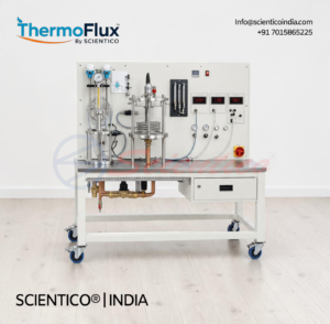
The Temperature Measurement Test Bench ThermoFlux 7011A is an experimental unit for demonstrating boiling and evaporation processes. This temperature measurement test bench uses a transparent pressure vessel, heating element, and water-cooled tube coil condenser in a closed circuit.
Product Overview
The ThermoFlux 7011A temperature measurement test bench visualizes boiling and evaporation in a transparent pressure vessel with 2180 mL capacity. A 300 W continuously adjustable heater drives evaporation. A copper coiled tube condenser closes the circuit, cooled by lab network water. Refrigerant R1233zd (GWP: 4) fills the system at 0.6 kg. A 4 bar safety valve and pressure switch protect the vessel. Sensors record pressure, cooling water flow rate, heating power, and temperatures at relevant points, with digital display. Software supports data acquisition via USB on Windows 11.
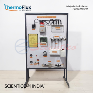
The Study of Fuel Injection Systems Trainer Thermoflux 12098 is a demonstration unit for studying diesel fuel injection technologies. This fuel injection systems trainer covers inline pump, rotary pump, and CRDI systems for IC engine laboratories.
Product Overview
The Thermoflux 12098 fuel injection systems trainer includes sectioned or working models of an inline fuel injection pump, a rotary (distributor) fuel injection pump, and a common rail direct injection (CRDI) system. Internal components and fuel flow are visible for classroom study. The trainer also covers fuel injection characteristics. It is mounted on a heavy duty fabricated structure with labeled components.
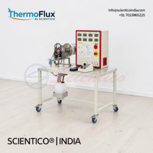
The Turbo Jet Engine Test Bench SCI-917 is an educational test bench for studying jet engine operation, thrust, and fuel-air ratio. This turbo jet engine test bench includes a compressor, annular combustion chamber, turbine, propelling nozzle, and integrated fuel and ignition systems.
Product Overview
The SCI-917 turbo jet engine test bench simulates an open cyclic process with ambient air intake. A single-stage radial compressor compresses air, which mixes with fuel and ignites in the annular combustion chamber. The turbine extracts energy to drive the compressor, and the nozzle expels gas to generate thrust. An electric starter enables automatic start-up. Maximum thrust is 82 N at 117,000 RPM. Real-time sensors record speed, temperature, pressure, and fuel consumption. Data displays digitally or transmits to PC via USB.

The Air Bag Trainer Torquemaster-39 is an educational apparatus for studying airbag system fundamentals as used in modern vehicles. This air bag trainer uses OEM components and replaces the exploding airbag with a light for safe classroom demonstration.
Product Overview
The Torquemaster-39 air bag trainer uses OEM components that function as in the original vehicle. A light replaces the airbag deployment. Students learn to identify main SRS components and study operation settings. OBDII scan tool readout supports OEM diagnostic trouble codes. Instrumentation demonstrates airbag deployment. The steering wheel removes and reinstalls safely during diagnosis. A built-in lockable manual fault box is included. The trainer operates from 220V AC, converted internally to 12V DC.
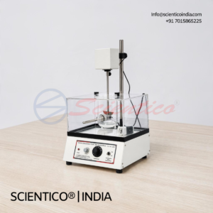
The Tablet Dissolution Test Apparatus Non-Digital PMSC 09 is a non-digital unit for tablet dissolution testing. It features a transparent perspex water bath with 500 W heater, speed regulation from 25 to 250 rpm, and a 1000 ml borosilicate glass vessel.
Product Overview
The PMSC 09 tablet dissolution test apparatus uses a transparent perspex water bath measuring 30 x 20 x 23 cm. A 500 W heater maintains 37 ±1°C. A speed regulator sets drive speed from 25 to 250 rpm. The 1000 ml borosilicate glass vessel includes a cover. A stainless steel basket with membrane fixing attachment holds the sample.

The Tablet Dissolution Test Apparatus 6 Station USP PMSC 06 is a six-station dissolution tester for USP testing. It features digital speed control from 25 to 160 rpm, PT-100 temperature sensing, and a microprocessor-based timer with alarm.
Product Overview
The PMSC 06 tablet dissolution test apparatus has six stations for USP testing. Speed control ranges from 25 to 160 rpm with ±1 rpm accuracy. The PT-100 sensor maintains temperature from 5°C above ambient to 45°C with ±0.5°C accuracy. A 350 W SS heater powers the clear acrylic bath measuring 300 x 200 x 200 mm. The microprocessor timer presets from 00:01 to 99:59 h with alarm. A 12 mm red LED display shows temperature, speed, and time. SS 316 baskets and paddles complete the assembly.
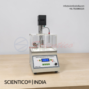
The Tablet Dissolution Test Apparatus IP Digital Single Unit PMSC 08 is a digital single-unit dissolution tester for IP testing. It features a transparent perspex water bath with cover, electronic speed control from 25 to 250 rpm, and a 1000 ml borosilicate glass vessel.
Product Overview
The PMSC 08 tablet dissolution test apparatus uses a transparent perspex water bath measuring 30 x 20 x 23 cm with cover. A 500 W heater maintains 37 ±1°C. A centrally mounted drive motor with electronic speed control runs from 25 to 250 rpm. The 1000 ml borosilicate glass vessel has a slightly concave bottom and flanged rim. A stainless steel cylindrical basket with membrane fixing attachment holds the sample. The display is digital.
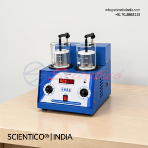
The Tablet Dissolution Test Apparatus IP Digital Double Unit PMSC 07 is a two-station digital dissolution tester for IP testing. It features transparent perspex water baths with 500 W heaters, 1000 ml borosilicate vessels, and electronic speed control from 25 to 250 rpm.
Product Overview
The PMSC 07 tablet dissolution test apparatus has two test stations. Each station uses a transparent perspex water bath with a 500 W heater maintaining 37 ±1°C. Vessels are 1000 ml borosilicate glass with concave bottoms and flanged covers. Electronic speed control adjusts drive speed from 25 to 250 rpm. Each station uses a stainless steel cylindrical basket with membrane fixing attachment. The display is digital.

disintegration testing as per IP, USP, and BP requirements. It features two basket assemblies, two independent thermostatic hot plates, and digital timer and temperature display.
Product Overview
The PMSC 05 tablet disintegration test apparatus tests tablets as per IP, USP, and BP requirements. The steel cabinet measures 14 x 12 x 8 inches and houses a geared motor drive. The stroke length is 7.6 cm at 30 strokes per minute. Two baskets with glass tubes and SS wire gauze run simultaneously. Two independently thermostatic hot plates rated 65 W each maintain 37 ±1°C. Digital timer and temperature display support test control. The unit includes two 1000 ml beakers.

The Tablet Disintegration Test Apparatus Non-Digital PMSC 04 is a non-digital unit for IP disintegration testing of tablets. It features a basket with glass tubes and SS wire gauze, a thermostatic hot plate, and a 1000 ml beaker.
Product Overview
The PMSC 04 tablet disintegration test apparatus tests tablets as per IP requirements. The stroke length is 7.6 cm at 30 strokes per minute. The basket assembly uses glass tubes with SS wire gauze. A thermostatic hot plate maintains 37 ±1°C. The unit includes a 1000 ml beaker.

The Rotary Tablet Punching Machine (Hand Operated) SCI 741 is a heavy single-punch tablet press for making tablets up to 1000 mg. It features automatic compression, ejection, feed, and removal with each wheel revolution.
Product Overview
The SCI 741 rotary tablet punching machine is a hand-operated single punch press. It produces tablets up to 1000 mg. Punch sizes of 6 mm, 9 mm, and 12 mm are available, selected according to tablet diameter. Each revolution of the wheel drives automatic compression and ejection, with automatic feed and removal of tablets. The unit has a heavy cast body with an eccentric pressure system. A stainless steel hopper connects through a rubber tube. Tablet thickness and hardness are set using nuts, locknuts, and the included set of two spanners. Dies and punches are chromium steel, mounted on a stand. This is the heavy model.
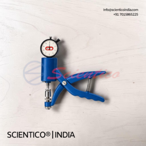
The Pfizer Type Tablet Hardness Tester PMSC 03 is a plier-type instrument for measuring tablet crushing strength. It features a dial gauge with 0.2 kg least count and a 20 kg safe testing force.
Product Overview
The Pfizer Type Tablet Hardness Tester PMSC 03 measures tablet hardness through crushing strength. The plier-type mechanism applies force to the tablet. The dial gauge displays the measured force. The safe testing force is 20 kg. Accuracy is ±0.2 kg. The least count is 0.2 kg. The tester handles tablets up to 25 mm diameter.

The Monsanto Type Tablet Hardness Tester PMSC 02 is a mechanical instrument for measuring tablet crushing strength. It features a 0 to 20 kg scale and an adjustable zero setting for different tablet sizes.
Product Overview
The Monsanto Type Tablet Hardness Tester PMSC 02 measures tablet hardness through crushing strength. The unit uses brass turned parts with heavy chrome plating. The graduated scale ranges from 0 to 20 kg in 1 kg divisions. The zero setting adjusts to accommodate different tablet sizes. The design supports quick hardness measurement of tablets.

The Friabilator (Friability Test Apparatus) Digital Single Drum PMSC 01 is a digital single-drum friabilator for tablet friability testing. It features a transparent perspex drum with cover and a digital preset timer with automatic stop.
Product Overview
The Friabilator Digital Single Drum PMSC 01 tests tablet friability with one transparent perspex drum. The drum measures 300 mm diameter by 35 mm deep and includes a cover. An S-shaped radial blade sits inside the drum. The drum runs at 25 ±1 rpm. A digital preset timer stops the unit automatically. The powder-coated mild steel cabinet houses the drive. The unit operates on 230 V AC, 50 Hz, single phase.

The Lyophilizer SCI 531 is a freeze dryer for lyophilizing samples in serum bottles, vials, ampoules, and other small glassware. It is available in 3 L and 6 L capacities.
Product Overview
The Lyophilizer SCI 531 freeze dryer uses a 316 stainless steel chamber with a powder-coated G.I. sheet outer body. A mechanical cooling system maintains condenser temperature at -50°C or -80°C. A solid-state controller with dual digital displays shows set and condenser temperatures. Stainless steel manifolds provide maximum vapour flow. Each 3/4 inch port has a quick-seal valve for attaching flasks. Manifold options include drum type, vertical type, or straight type. The unit ships with a suitable vacuum pump.
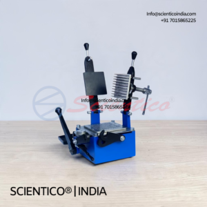
The Capsule Filling Machine SCI 742 is a manual capsule filling machine for lab-scale formulation work. This capsule filling machine processes 100 capsules per batch with hand-operated control.
Product Overview
The SCI 742 is a hand-operated capsule filling machine built for laboratory use. Each batch fills 100 capsules. The unit accepts standard lab capsule sizes. Its compact lab scale design suits small formulation studies. The machine supports capsule filling for formulation research.
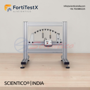
The Two Hinged Arch Apparatus FortiTestX-49 studies two-hinged arch behavior under various loading conditions. Integrates automatic data acquisition, PC interface and ADA software for real-time data logging, graphical analysis and automated calculations.
Product Overview
The Two Hinged Arch Apparatus FortiTestX-49 investigates load distribution, support reactions and structural behavior of two-hinged arches. Automatic data acquisition unit connects to PC for enhanced analysis. ADA software provides real-time data logging, graphical plotting and calculations. Premium construction with durable materials ensures reliable performance across repeated experiments. Students measure reaction forces and moments at hinged supports, track deflection at multiple arch locations, and compare experimental results with theoretical calculations.
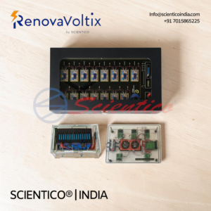
The Battery Management System (BMS) Trainer RVX 121 is an educational apparatus for studying and testing lithium-ion battery management systems. This BMS trainer features BMS board with PC software and Bluetooth app, lithium battery emulator with individual cell voltage control, 48V lithium battery, battery discharger, and protection board test equipment for comprehensive battery management system training.
Product Overview
The RVX 121 battery management system trainer comprises BMS board supporting 15-cell 48V lithium systems with PC-based software and mobile Bluetooth app for system monitoring. Lithium battery emulator board provides 15 voltage channels (1.2V to 4.9V per cell) with 2mV accuracy and 1000mA per channel output for safe BMS testing without live battery risk. Real 48V 6Ah lithium iron phosphate battery provides actual battery testing capability with four integrated temperature sensors. Battery discharger unit rated 1kW enables constant current discharge testing with 0-20A range, ±0.2% precision, and real-time data logging at 2-second intervals up to 999 hours. Hot air gun with temperature probe (100-480°C adjustable) tests temperature sensor functionality. Protection board test system performs precise and quick testing of over-charge, over-discharge, short-circuit, and cell balancing protection functions. Quick test mode enables rapid production testing. Precise test mode provides 5mV voltage accuracy for development and debugging. High-current module supports 120A testing with 0.1A accuracy. Short-circuit module uses super-capacitor to instantly replicate battery voltage conditions. Individual cell self-consumption testing supports 1-16 cell strings. Loop resistance measurement (0-500mΩ) tests internal battery protection circuit quality.

The Solar Educational Kit RVX 118 is an educational apparatus for studying solar energy applications and photovoltaic cell characteristics. This solar educational kit features 4V solar panel with battery charging capability and multiple appliance connections for demonstrating practical renewable energy utilization.
Product Overview
The RVX 118 solar educational kit demonstrates solar energy applications across consumer and industrial uses. 4V solar panel generates electrical power from incident solar radiation for direct appliance operation or battery charging. Kit includes battery charger circuit for energy storage. Connected appliances demonstrate practical solar energy use including vehicle operation, pump activation, traffic light control, and fan operation. Solar irradiance meter measures incident light intensity to correlate with electrical output performance. V-I characteristic measurement capability enables investigation of solar panel voltage and current relationships under varying illumination conditions. Modular design enables flexible demonstration configurations. Complete cable set facilitates component interconnection. Instruction manual provides step-by-step experiments and application examples. Compact portable design suits classroom and laboratory settings.
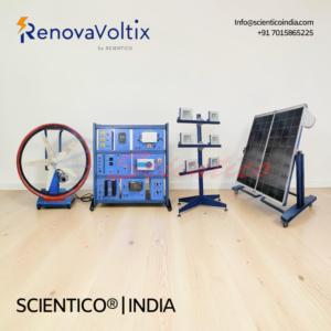
The Wind / Solar Hybrid Energy System RVX 101 is an educational apparatus for studying renewable energy generation from combined wind turbine and solar module sources. This wind solar hybrid energy system demonstrates how wind and solar resources integrate in consumer and industrial markets to supplement power needs and reduce dependence on non-renewable fuels.
Product Overview
The RVX 101 wind solar hybrid energy system comprises moveable solar module frame with integrated lighting and light intensity control, portable wind turbine frame with AC 3-phase motor and motor driver, wind solar hybrid controller, variable resistive load, electric brake, measurement module with RPM sensor, and complete cable set. Solar module operates with adjustable inclination angle relative to light source for efficiency optimization. Artificial light source module with intensity control enables indoor laboratory operation. Wind turbine operates via AC motor driver with variable speed control. Hybrid controller manages simultaneous power input from solar and wind sources with charge controller function. Variable resistive load enables investigation of output under different electrical loads. Electric brake provides rapid wind turbine stop. Measurement module monitors wind turbine RPM, solar voltage output, wind turbine voltage output, current, and load resistance. 12VDC battery (24VDC available, user-supplied) stores energy from both sources. Optional LABVIEW DAQ software monitors and logs all electrical and environmental parameters via Windows interface.

The PEM Electrolyzer Trainer RVX 134 is an educational apparatus for studying proton exchange membrane water electrolysis and hydrogen production from renewable energy sources. This PEM electrolyzer trainer demonstrates efficient clean hydrogen generation using solar, wind, or grid power with comprehensive safety monitoring and hydrogen storage capability.
Product Overview
The RVX 134 PEM electrolyzer trainer features 500W electrolyzer with five cells and 22-25 cm² active area producing up to 100 L/h hydrogen from water electrolysis. Proton exchange membrane splits water into hydrogen and oxygen at bipolar plates with platinum-coated titanium anode felt and tin-coated titanium plates. Electrolyzer operates at 0-20 bar hydrogen pressure with deionized water consumption of 0.17 L/h at 100 L/h minimum flow rate. Operating temperature range 30-70°C maintained via integrated heat exchanger with water-cooling closed-circuit system including circulation pump and ion filter, or air-cooling option with controllable fan and damper. Voltage range 7.5 to 12.5VDC with maximum current 15-60A via constant current and constant voltage controller power supply unit. Solar/wind charge controller with MPPT technology and accumulator battery manages renewable energy storage and electrolyzer power supply. Hydrogen drying section removes moisture. Comprehensive safety monitoring includes temperature, pressure, and flow sensors at all stages, H2 leakage detection via LEL sensor meeting minimum standards, water quality detector, dry run protection, gas port open detection, and over-pressure relief. Optional metal hydride cylinders (300L or 600L capacity) store generated hydrogen. Optional LABVIEW DAQ software monitors and logs voltage, current, temperature, pressure, and flow measurements via USB interface.
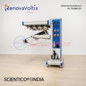
The Solar Cell Measurements RVX 133 is an educational apparatus for studying photovoltaic solar cell behavior under varying illumination and temperature conditions. This solar cell measurements trainer features four monocrystalline silicon cells with adjustable lighting, Peltier temperature control, and patch panel for investigating cell interconnection effects and bypass diode functionality.
Product Overview
The RVX 133 solar cell measurements trainer comprises four 125x125mm monocrystalline silicon solar cells with 3W maximum output and 70% fill factor. Adjustable lighting unit with four 100W lamps provides variable illuminance control. Peltier module maintains precise cell temperature from 20°C to 60°C. Patch panel enables flexible cell interconnection in series or parallel configurations with integrated bypass diodes for shading loss analysis. Integrated rheostat enables manual current-voltage characteristic curve recording. Built-in measuring unit detects voltage and current across full operating range. Reference cell functions as illuminance sensor. Temperature sensors monitor cell temperature. Corresponding sensors detect voltage, current, and illumination at all test points. Included cable set enables various interconnection configurations. Optional automated measurement function enables software-controlled load pattern definition for characteristic curve capture. Stand-alone operation via manual rheostat or computer-controlled via optional LABVIEW DAQ software with USB data acquisition and Windows compatibility. All measured data logging and visualization available through optional software.
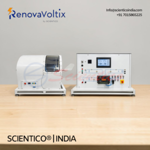
The Wind Energy Trainer with Wind Tunnel RVX 112 is an educational apparatus for studying kinetic wind energy conversion to electrical energy with controlled wind conditions. This wind energy trainer features enclosed wind tunnel with axial fan, horizontal axis wind turbine with interchangeable blades, and stand-alone electrical system for energy generation and storage.
Product Overview
The RVX 112 wind energy trainer with wind tunnel comprises rust-free painted steel tunnel (600-650mm diameter, 300-400mm length) housing axial fan and horizontal axis wind turbine. Axial fan delivers up to 3.5 m³/s volumetric flow at 1.1 kW maximum power with adjustable speed for wind velocity variation from 0.3 to 50 m/s. Flow straightener maintains smooth, low-turbulence airflow. Wind turbine rotor of 600mm diameter operates at up to 1400 rpm. Interchangeable blade system allows testing of different blade configurations, orientations, and student-designed 3D-printed blades. Generator produces 60W maximum output at 12VDC with 5A maximum charging current. Charge controller regulates energy storage in 12VDC accumulator battery (user-supplied, 8Ah capacity). Stand-alone system operates independent of grid. Five 15W incandescent bulbs serve as electrical load or external load connection available. Wind velocity sensor measures air flow (0.3 to 50 m/s). Rotor speed sensor measures rotational speed (0 to 3000 min⁻¹). Voltage sensor measures output (0 to 20VDC). Current sensor measures charging current (0 to 35A). Digital displays show all measurements. Control unit includes emergency push button safety feature. Optional LABVIEW DAQ software enables wind turbine characterization analysis.
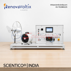
The Energy Conversion in a Wind Power Plant RVX 104 is an educational apparatus for studying transformation of kinetic wind energy into electrical energy in stand-alone systems. This energy conversion wind power plant features laboratory-scale wind turbine with axial fan wind source, generator, accumulator storage, and electrical load measurement.
Product Overview
The RVX 104 energy conversion wind power plant comprises axial fan providing variable-speed wind source, laboratory-scale wind turbine rotor with 600mm diameter, generator producing 60W maximum output at 12VDC, and charge controller managing energy storage. Axial fan delivers up to 3.5 m³/s volumetric flow at 1.1 kW maximum power with continuously variable speed control enabling wind velocity adjustment from 0.3 to 50 m/s. Wind turbine rotor operates at up to 1400 rpm. Generator converts kinetic energy to electrical energy at 12VDC with 5A maximum charging current. 12VDC accumulator battery stores electrical energy (battery arranged by user due to export regulations). Charge controller regulates energy storage and discharge. Control unit integrates five 15W incandescent bulbs as electrical load consumers or external load connection capability. Stand-alone system operates independently without grid connection. Wind velocity sensor measures air flow in front of rotor. Speed sensor measures rotor rotational speed (0 to 3000 min⁻¹). Voltage sensor measures output (0 to 20VDC). Current sensor measures charging current (0 to 35A). Digital displays show all measured values. Optional LABVIEW DAQ software enables energy balance analysis and efficiency calculation.

The Domestic Water Heating with Flat Collector RVX 131 is an educational apparatus for studying solar thermal energy collection and domestic hot water heating systems. This domestic water heating flat collector unit features adjustable frame-mounted flat plate collector with instrumentation console for performance monitoring across various operating conditions.
Product Overview
The RVX 131 domestic water heating flat collector system comprises a 2 m² flat plate solar collector mounted on adjustable metallic structure with lockable castor wheels. Anodized aluminum construction with copper pipes wrapped in insulating material and tempered glass cover enables efficient solar energy capture. Instrumentation console displays circulating water flow rate, inlet and outlet temperatures, ambient temperature, and incident solar radiation via digital indicators. Solar circulation pump with PWM control delivers up to 7 LPM flow. Flow sensor measures 1 to 15 LPM in primary circuit. Thermocouples positioned at various points monitor system temperatures from -100°C to 800°C. Manometer displays system pressure (0 to 4 bar). Expansion tank and de-airing valve manage system pressure and air removal. Protractor with integral level indicator (1° increments) enables precise collector positioning. Optional solar irradiance sensor measures incident energy for efficiency calculation. Cooling water flow adjustment allows investigation across multiple operating conditions. Optional artificial light source module enables indoor operation. Optional storage tank available in 50L or 100L with thermostat control and 1000W auxiliary heater. Optional LABVIEW DAQ software with LAN/USB data acquisition enables daily performance variation analysis.
The Hot Water Central Storage Module with Controller RVX 130 is an educational apparatus for studying heat generation, storage, and distribution from renewable energy sources. This hot water central storage module integrates buffer and bivalent storage options with pump, 3-way valve, and safety equipment for modular thermal system testing.
Product Overview
The RVX 130 hot water central storage module serves as the core integration point for modular renewable energy heating systems. Two storage tank options accommodate different applications: 100L buffer tank with single heat exchanger for simple storage circuits, or 200L bivalent tank with dual heat exchangers for complex multi-source systems. Circulating pump delivers up to 3.1 m³/h flow at 5m maximum head with variable speed control. Driven 3-way valve directs flow to different circuits based on control logic. Temperature sensors monitor buffer and room conditions. Two pressure sensors provide system safety monitoring. Flow meters quantify heat transfer rates. Quick-release couplings on front panel enable rapid hydraulic connection to solar thermal, heat pump, and fan heater modules. Pressure relief and bleed valves ensure safe operation. All components operate at maximum 96°C temperature and 5 bar pressure. Optional LABVIEW DAQ software transmits temperature, pressure, and flow data to external controller for real-time system analysis.

The Fan Heater Unit RVX 129 is an educational apparatus for studying fan convector heating and cooling applications in thermal systems. This fan heater unit functions as heat source for room heating or heat sink for heat pump systems with dual-speed axial fan and integrated temperature measurement.
Product Overview
The RVX 129 fan heater unit comprises fan convector, pipework, quick-release couplings with shut-off valves, and temperature sensors for dual-mode operation. Axial fan with two selectable speed settings from 0 to 1400 rpm delivers flow rates up to 1200 m³/hr. Heat exchanger provides 2kW cooling capacity at maximum 10 bar operating pressure. Dual temperature sensors on feed and return pipes measure thermal gradient. Three temperature sensors monitor system performance. Flow rate measurement ranges from 10 to 3000 L/h. Quick-release couplings enable rapid connection to modular heat pump and heating systems. The fan heater unit achieves efficient room heating at lower circuit temperatures compared to traditional radiators. As air heat exchanger in heat pump systems, it absorbs ambient air heat when groundwater or geothermal sources are unavailable. Optional LABVIEW DAQ software transmits temperature and flow data to external controllers for energy analysis.
The Underfloor Heating / Geothermal Energy Absorber RVX 128 is an educational apparatus for studying heat transfer in underfloor heating systems and geothermal energy applications. This underfloor heating geothermal energy absorber functions as heat sink or heat source in modular system configurations with selectable pipe lengths and integrated flow measurement.
Product Overview
The RVX 128 underfloor heating geothermal energy absorber features spiral or wound piping systems for heat transfer simulation at substantially lower temperatures than traditional radiators. Three selectable pipe lengths (10m, 20m, and alternative configurations) with 2mm thickness enable variable heat transfer experiments. Water-filled tank surrounds piping for thermal contact. Temperature sensors on feed and return pipes measure thermal gradient. Integrated flow meter quantifies flow rate for energy balance calculation. Measurement data transmits to external controller via dedicated connections. The apparatus operates as heat sink in heating mode or heat source when employed in heat pump systems with reversed heat transport direction. Modular design integrates with heat pump trainers and solar thermal systems. Optional LABVIEW DAQ software processes temperature and flow data for heat quantity determination.
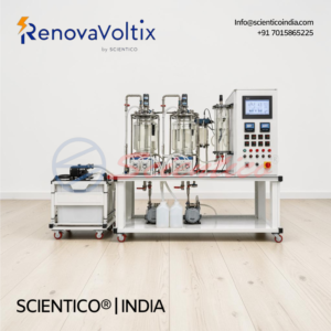
The Biogas Process Trainer RVX 127 is an educational apparatus for studying anaerobic digestion and biogas generation through microbial breakdown of biodegradable material. This biogas process trainer enables investigation of single-stage or two-stage anaerobic digestion with temperature, pH, and biogas composition monitoring across psychrophilic, mesophilic, and thermophilic operating ranges.
Product Overview
The RVX 127 biogas process trainer includes two 7.5L packed anaerobic digesters with 25mm diameter bacto ball reactor packing and individual heating blankets with thermostats for temperature control from 0 to 100°C. Four peristaltic pumps manage substrate feed, acid addition, base addition, and inter-digester transfer through a 2L buffer tank. Two pH meters and temperature sensors monitor each digester stage. Biogas generated flows to two volumetric tanks measuring gas volume via water displacement. Industrial-grade methane (CH4) and carbon dioxide (CO2) sensors with 0 to 100% range analyze biogas composition. Electronic console displays temperature, pH, methane, and CO2 measurements. Acid and base storage vessels maintain pH control capability. Two 3L polyethylene vessels provide acid and base supply. Optional LABVIEW DAQ software transmits all sensor data to PC. Anodized aluminum structure with stainless steel metallic elements ensures durability.

The Bioethanol Process Trainer RVX 126 is an educational apparatus for studying bioethanol production through mashing, fermentation, and distillation processes. This bioethanol process trainer enables investigation of liquefaction, saccharification, fermentation, and distillation stages from raw materials to ethanol conversion on laboratory scale.
Product Overview
The RVX 126 bioethanol process trainer consists of three main components: stainless steel mash tank with enzyme addition capability, fermentation tank with yeast fermentation monitoring, and borosilicate glass distillation unit. Mash tank converts starch to glucose through alpha-amylase and glucoamylase enzyme addition with pH control via acid and base circuits. Temperature sensors and pH meter monitor mash properties. Fermentation tank receives mashed solution and converts sugars to ethanol and CO2 via yeast addition, with CO2 concentration measurement and temperature monitoring. Both tanks heat indirectly through hot water jackets with integrated thermostatic bath and circulation pump. Distillation unit includes 5L reactor flask with 1500W heating mantle, Vigreux distillation column, Liebig-West condenser, cold finger dephlegmator, and decanting funnel. Two centrifugal pumps transfer solutions between stages. Motorized valves control hot water flow. Electronic console displays temperature, pH, and CO2 measurements. Optional LABVIEW DAQ software transmits sensor data to PC.

The Biodiesel Process Trainer RVX 125 is an educational apparatus for studying biodiesel production from raw vegetable oils through two defined process stages. This biodiesel process trainer allows investigation of production parameters, process variables, and biodiesel quality assessment using mixing, reaction, separation, and washing techniques.
Product Overview
The RVX 125 biodiesel process trainer produces biodiesel from raw vegetable oil through two stages: Stage I mixes raw materials with stirring and homogenous heating in a 10L glass reactor with temperature control. Stage II separates products through two-phase decantation and washing via ion exchange resin. The system includes a 30L oil tank with mesh filter, positive displacement dosing pump for methylate addition at 20 LPH, single-phase recirculation pump for diesel at 25 L/min, and integrated separation tanks for glycerin and biodiesel collection. Stainless steel construction with polymer hoses rated for fuels ensures durability. Digital balances measure biodiesel and glycerin mass. Temperature sensor with digital display monitors reactor conditions. Ion exchange resin purification compartment provides washing. Control panel integrates heating element switch, pump regulator valve, and load displays. Mobile design with wheels enables easy repositioning. Optional DAQ software in LABVIEW transmits measurement data to PC.
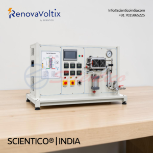
The Fuel Cell Energy Training System RVX 123A is an educational apparatus for investigating polymer-membrane fuel cells with direct chemical-to-electrical energy conversion. This fuel cell energy training system operates in combined heat and power generation with 200W nominal output, hydrogen from pressure vessel, and oxygen from ambient air, controlled via integrated electronic load.
Product Overview
The RVX 123A fuel cell energy training system features a 200W nominal output polymer-membrane fuel cell with voltage range 13.75 to 23.75V and current 13.3 to 16.6A. Hydrogen supply uses standard pressurized vessel with high-pressure reducing valve and solenoid valve. Oxygen draws directly from ambient air. Integrated 250W electronic resistive load controlled via touch LCD allows precise operating point adjustment. Thermal energy from cell cooling dissipates through cooling circuit and integrates into instrumentation analysis. Water separator collects accruing water with configurable purge valve in dead-end mode. Moisture regulation occurs automatically via operating temperature and air flow without external humidification. All measured values transmit to PC via included DAQ system and LABVIEW software.
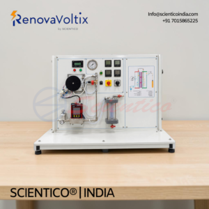
The Fuel Cell Energy Training System RVX 123 is a comprehensive educational apparatus for investigating polymer-membrane fuel cells and their direct conversion of chemical energy into electrical and thermal energy. This fuel cell energy training system operates in combined heat and power generation mode with hydrogen supply from a pressure vessel and oxygen from ambient air, controlled via integrated electronic load regulation.
Product Overview
The RVX 123 fuel cell energy training system enables students to study energy conversion principles, fuel cell design, and operating parameter relationships in a hands-on laboratory setting. The apparatus features a polymer-membrane fuel cell with nominal 100W output operating at 8.3A and 12V, capable of simultaneous electrical and thermal power generation. Hydrogen is supplied via standard pressure vessel with integrated high-pressure reducing valve, while oxygen draws directly from ambient air. An integrated electronic load allows precise adjustment of all operating points with accurate characteristic recording. Moisture regulation occurs automatically through operating temperature and air flow control without requiring external humidification. A comprehensive sensor suite monitors flow rate, pressure, temperature, voltage, and current strength. All measured values are recorded for fuel cell energy balance calculation, with optional transmission to PC via DAQ system and LABVIEW software.
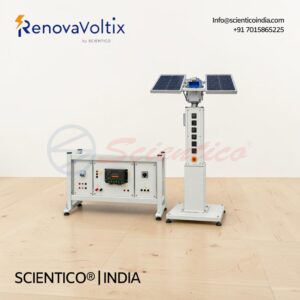
The Solar Tracking Control Trainer RVX 122 is a hands-on educational apparatus designed to estimate solar generation quantity in relation to solar altitude. This solar tracking control trainer enables PC-controlled motor positioning through e-compass integration for multi-directional movement, covering top-to-bottom and left-to-right tracking capabilities.
Product Overview
The RVX 122 solar tracking control trainer facilitates comprehensive study of sun-tracking system principles and solar energy optimization. The apparatus combines a 40W solar cell unit, DC geared tracker motor, PWM charge controller, and terminal box with integrated sensors to measure real-time efficiency variations between tracked and untracked PV panel output. Students can simulate cardinal plane positioning, calculate sun location instantaneously at any time and geographic location, and evaluate tracking system performance through hands-on experimentation. The trainer operates on 12V or 24V DC input with auto-select voltage capability and includes specialized DAQ software built on National Instruments LABVIEW environment for measurement and result calculation.
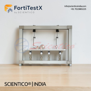
The Influence Line Apparatus FortiTestX-47 is designed for studying reactions under various load conditions at all supports along a three-span bridge structure. This Influence Line Apparatus features a cantilever end section and suspended center section with adjustable support locations, vertical force measurement at supports, and dial indicator deflection measurement for comprehensive structural analysis and influence line plotting.
Product Overview
The Influence Line Apparatus FortiTestX-47 demonstrates how loads moving across a bridge structure affect support reactions and internal reactions between cantilever and suspended sections. The three-span bridge comprises two end spans of 250 mm each and a center suspended span of 150 mm. The bridge structure allows investigation of influence lines for supports and internal reactions as loads traverse the beam. Four vertical force supports (ST 124 type) measure reaction forces at all support locations. Two rolling loads enable students to apply load at different positions across the bridge span. Two dial indicators (ST 131 type) measure deflection of the bridge at selected locations. The support locations are adjustable to enable variation of span configurations for different influence line studies. Vertical force supports provide direct measurement of loads transferred to each support point. The apparatus enables students to plot influence lines by recording reactions at each support as loads move progressively across the bridge structure. An instruction manual provides guidance on apparatus operation and experimental procedures. Optional learning software supports both online and offline training with data calculation and analysis by manual entry from analog measuring instruments. A computer-assist version includes digital sensors with data acquisition, real-time data logging, graphical analysis, data export capability, and optional WiFi remote monitoring on iOS and Android smartphones.
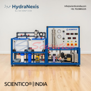
The Brackish Water Reverse Osmosis Training System HydraNexis HNX-05 is a compact, mobile, modular laboratory-scale RO system designed for practical training in brackish water treatment, membrane separation, desalination and water quality monitoring. This Brackish Water Reverse Osmosis Training System processes feed water up to 10,000 ppm TDS with nominal treated-water production of approximately 500 L/day using a polyamide spiral-wound membrane and computerized process monitoring.
Product Overview
The Brackish Water Reverse Osmosis Training System HydraNexis HNX-05 incorporates raw-water storage, pretreatment, antiscalant dosing, high-pressure RO separation, post-treatment, product-water storage, process instrumentation and computerized monitoring. The system is mounted on a heavy-duty mobile frame with quick-connect hydraulic connections, dedicated sampling points and CIP provisions. Two polyethylene storage tanks (approximately 500 L each) provide raw-water and product-water capacity. A raw-water transfer pump feeds pretreated water to the RO system. Pretreatment includes a 5 micron polypropylene sediment cartridge filter, granular activated carbon filter, and integrated antiscalant chemical dosing system. The RO membrane is a high-rejection thin-film composite spiral-wound membrane with approximately 1.2 m² active area. A high-pressure piston pump with active pulsation damper provides approximately 585 L/h maximum flow at up to 140 bar system pressure, with 40 bar maximum operating pressure. Separate flow measurement for permeate and concentrate/reject streams enables recovery analysis. Digital TDS/conductivity analyzer and pH measurement monitor water quality across feed, permeate and concentrate streams. A carbon block polishing filter provides final post-treatment. The centralized control panel features automatic tank-level management, digital instrumentation display, high- and low-pressure protection, emergency stop, and IP65-rated electrical enclosure. Dedicated CIP ports enable connection of external membrane-cleaning tanks for practical training in membrane maintenance and chemical cleaning. Vibration-isolation mounts minimize pump noise during laboratory operation. Quick-connect hydraulic fittings allow modular reconfiguration for varied training exercises
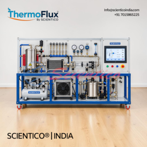
The Advanced Thermodynamics Trainer Unit ThermoFlux-2920 is a computerized, modular laboratory training system for practical investigation of thermodynamic principles and energy-transfer processes. This Advanced Thermodynamics Trainer Unit combines controlled air supply, heating and cooling arrangements, heat-transfer and calorimetry modules, expansion/compression experimentation, multi-channel measurement, airflow monitoring, and computer-based data acquisition for comprehensive thermodynamics education.
Product Overview
The Advanced Thermodynamics Trainer Unit ThermoFlux-2920 enables experimental study of ideal-gas behavior, isothermal, adiabatic and polytropic processes, heat and work interactions, thermal equilibrium, energy balance, efficiency, calorimetry, heat transfer and basic thermodynamic cycles. The system features an integrated air supply system with pressure regulation, filtration and safety controls, operating from atmospheric pressure to minimum 8 bar. A minimum of 6 digital temperature measurement channels using thermocouples or RTDs monitor thermal processes. Digital pressure sensors with analog pressure gauges display system pressures. An integrated airflow measurement system quantifies mass flow for process analysis. An electrically controlled heating unit with adjustable output (minimum 500 W) provides thermal input with temperature control and over-temperature protection. An integrated air- or water-cooling system enables controlled thermal experiments. Heat exchanger and calorimetry modules demonstrate heat transfer and energy exchange. An expansion/compression module enables investigation of compression and expansion processes with pressure-volume measurements. A microprocessor/PLC-based control system with PC interface manages all Advanced Thermodynamics Trainer Unit functions. Real-time PC-based data acquisition logs temperature, pressure and flow data simultaneously. Software enables graphical analysis, energy calculations, efficiency analysis, theoretical-experimental comparison and report generation. A heavy-duty powder-coated steel frame with lockable castors provides stable, mobile laboratory installation. Safety features include over-temperature protection, over-pressure protection, emergency stop, pressure relief valve and electrical overload protection.
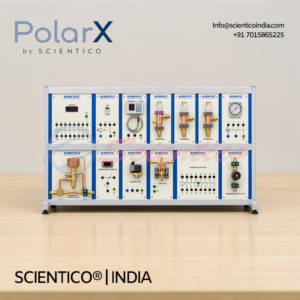
The Refrigeration Components for Advanced Experiments PolarX-1015 enables sophisticated refrigeration system design and operation using complex industrial components. This advanced system includes capacity controllers, intake pressure controllers, defrost timers, four-way reversing valves, and refrigeration controllers for multi-circuit experimentation and hot gas defrosting procedures on real equipment.
Product Overview
The Refrigeration Components for Advanced Experiments PolarX-1015 is designed for setup of complex refrigeration circuits and advanced experiments using sophisticated refrigeration components. The system includes a capacity controller to regulate compressor output, an intake pressure controller to maintain suction pressure, a defrost timer for automatic defrosting cycles, and a four-way reversing valve enabling circuit reversal for hot gas defrosting of iced-up evaporators. A refrigeration controller manages overall system operation. Manometers indicate high- and low-side pressure ratios throughout the refrigeration components circuit. Pressure and temperature measuring instruments enable monitoring of refrigerant state and plotting on a log p-h diagram using laboratory thermometers. Additional refrigeration components include electric thermostats, manual expansion valves, post-injection valves, solenoid valves with coils, power and auxiliary contactors, and time relays. The four-way reversing valve temporarily converts the evaporator to a condenser for defrosting frozen evaporators through hot gas defrosting methods. Technical drawings and operating instructions guide students through complex circuit design, component operation, adjustment procedures, and fault-finding in refrigeration components systems.
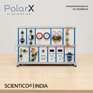
The Refrigeration Components for Basic Experiments PolarX-1011 enables students to design and operate simple refrigeration circuits using real industrial components. This system provides practice-oriented learning with genuine refrigeration equipment, high- and low-pressure manometers, temperature measurement instruments, and flow monitoring for comprehensive refrigeration cycle understanding.
Product Overview
The Refrigeration Components for Basic Experiments PolarX-1011 is designed for setup of simple refrigeration circuits and hands-on experimentation using authentic industrial refrigeration components. The system includes expansion elements, filters, switches, and thermostats for circuit assembly. A superheater or equivalent heat exchanger ensures complete refrigerant evaporation before compressor intake while providing supercooling of liquid refrigerant upstream of the expansion element. A flow meter monitors expansion element control behavior. High- and low-pressure manometers demonstrate pressure ratios throughout the refrigeration circuit. Pressure and temperature measuring instruments enable tracking of refrigerant state and plotting of the refrigeration cycle on a log p-h diagram using laboratory thermometers. Components include a sight glass with filter/drier, thermostatic and pressure-controlled expansion valves, delivery and intake manometers, superheater, liquid separator, 3-pin circuit breaker, and electric two-point thermostat with switch hysteresis. Assembly aids and technical drawings support circuit design, component operation, troubleshooting, and fault-finding activities for comprehensive refrigeration components learning.
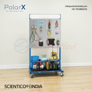
The Refrigerant Recovery and Charging Learning Systems for R-134a / R-410a PolarX-1098 provides hands-on HVACR training through integrated service equipment and interactive courseware. Available in two configurations, the PolarX-1098-A targets R-134a systems while the PolarX-1098-B addresses R-410a refrigerant handling, enabling technicians to master refrigerant recovery and charging skills required by employers.
Product Overview
The Refrigerant Recovery and Charging Learning Systems for R-134a / R-410a PolarX-1098 combines genuine service equipment with multimedia courseware to bridge theory and practical application. Each workstation includes a mobile configuration, recovery machine, manifold gauge set, charging hose set, temperature probe, valve core removal tools, submersible cooler, electronic scale, and filter dryer. The PolarX-1098-A operates with R-134a refrigerant, while the PolarX-1098-B includes a liquid vaporizer for R-410a handling. Both systems feature comprehensive multimedia curriculum covering refrigerant fundamentals, environmental regulations, leak detection methods (ultrasonic, dye, halide), pressure and temperature measurement, compound gauge operation, recovery and recycling procedures, refrigerant handling and storage, charging methods, and blended refrigerant techniques. The PX-1098 interactive courseware includes instructor guide, installation guide, and student reference guide. Requires EPA 608 Certification or equivalent local protocol for instructors. Operates on single-phase 120V / 60Hz electrical supply. Customer supplies refrigerant and recovery tank.
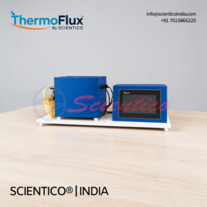
The Thermal Conductivity of Insulating Slab ThermoFlux-2909 is designed to determine thermal conductivities of insulating materials in slab form under controlled laboratory conditions. This apparatus uses a dual-heater system with cooling plates to establish precise temperature gradients across insulating slab specimens, enabling accurate thermal property measurement.
Product Overview
The Thermal Conductivity of Insulating Slab ThermoFlux-2909 features a central main heater and ring guard heater sandwiched between two identical insulating slab specimens. Cooling plates are positioned on either side of the specimen assembly. The specimens are clamped between the heaters to ensure unidirectional heat flow through the insulating slab, eliminating lateral heat loss. The entire assembly is housed in a chamber and surrounded by ceramic wool insulation to minimize external heat loss. The ring guard heater maintains temperature balance at the specimen edges, ensuring accurate one-dimensional heat conduction measurement through the insulating slab. Water cooling at approximately 5 liters per minute circulates through the cooling plates to maintain stable boundary conditions. The apparatus operates on single-phase, 220 V AC supply at 2 amperes.
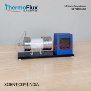
The Thermal Conductivity of Metal Bar ThermoFlux-2908 is designed to determine the thermal conductivity of metal materials by measuring heat transmission through a test bar under controlled conditions. This apparatus demonstrates how thermal energy transfers through molecular motion in solid materials using a heated copper bar with thermocouples positioned along its length.
Product Overview
The Thermal Conductivity of Metal Bar ThermoFlux-2908 consists of a mild steel test bar, 25 mm diameter, with thermocouples mounted along its length to measure temperature at respective positions. A band heater at one end supplies controlled thermal input, while a heat sink at the opposite end dissipates heat. The test portion is well insulated to minimize heat loss through the sides. A digital voltmeter (0-199.9 volts) and digital ammeter (0-1.999 amp) measure heater input power. A dimmer stat allows variable adjustment of heat input for different thermal load experiments. A multi-channel digital temperature indicator displays all thermocouple readings simultaneously. Measuring flask and stop clock enable precise thermal data collection. Water supply at 2 liters per minute constant head flows through the heat sink for consistent cooling conditions.
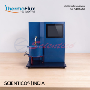
The Stefan Boltzman Apparatus ThermoFlux-2901 is designed to determine the Stefan Boltzman constant through controlled radiation heat transfer experiments. This apparatus demonstrates the fundamental phenomenon of heat transfer by radiation using a heated copper hemisphere and a small test disc as the radiation receiver.
Product Overview
The Stefan Boltzman Apparatus ThermoFlux-2901 consists of a 200 mm diameter copper hemisphere fixed on a bakelite plate, surrounded by a hot water jacket. A hot water tank with integrated heater, positioned above the hemisphere, supplies heated water to the jacket, raising the hemisphere temperature. Heat transfers from the heated hemisphere to a small copper test disc (20 mm diameter, 1.5 mm thick) placed at the hemisphere center through radiation only. A thermocouple at the disc center measures disc temperature. Four thermocouples distributed on the hemisphere surface measure average hemisphere temperature. A built-in timer enables temperature measurements at constant intervals. A multi-channel digital temperature indicator simultaneously displays all thermocouple readings, allowing precise Stefan Boltzman constant determination by correlating radiation heat transfer to temperature differences.
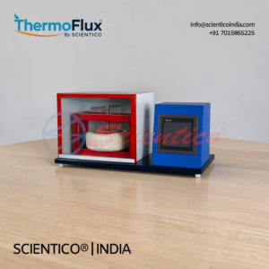
The Heat Transfer through Composite Wall Apparatus ThermoFlux-2904 is engineered to determine total thermal conductivity of a composite wall and plot temperature gradients along the composite wall structure. This apparatus enables accurate measurement of heat transfer characteristics across layered materials through controlled experimental conditions.
Product Overview
The Heat Transfer through Composite Wall Apparatus ThermoFlux-2904 consists of a central nichrome wire heater wound on mica and sandwiched between two aluminum plates. Three identical slabs of M.S., Bakelite, and Press wood, each 200 mm diameter, are stacked on both sides of the heater to form a composite wall structure. A hand press ensures perfect contact between slabs. Thermocouples embedded at slab interfaces measure temperatures at respective surfaces. Digital voltage (0-199.9 volts) and ammeter (0-1.999 amp) readings allow precise heater input control via dimmer stat. A multi-channel digital temperature indicator logs all thermocouple data. The assembly is housed in an enclosure with a Perspex window for observation. Experiments can be conducted at various input levels for comparative thermal analysis.
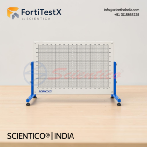
Statics Work Panel – FortiTestX – 53 is a robust steel panel system designed to support complete Statics Fundamentals range of experiment kits. This large-format work panel features a metric grid for precise positioning and magnetic compatibility, enabling educators to conduct comprehensive demonstrations of static forces and equilibrium principles in classroom environments.
Product Overview
The Statics Work Panel – FortiTestX – 53 provides a stable mounting surface for all Statics Fundamentals kits, including Equilibrium of a Rigid Body (FortiTestX – 51), Equilibrium of a Beam (FortiTestX – 52), Equilibrium of Forces (FortiTestX – 50), and Suspension Cable Demonstration apparatus. The large size makes it ideal for classroom demonstrations visible to multiple students simultaneously. A clear metric grid enables repeatable, accurate positioning of experiment components and facilitates precise measurement recording. The robust steel construction and magnetic surface allow students to rapidly assemble, reconfigure, or remove experiments without tools, reducing setup time and enabling efficient lesson flow.
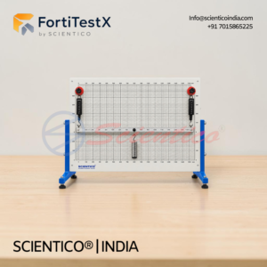
Equilibrium of a Beam – FortiTestX – 52 is a hands-on kit designed for statics education using the Work Panel (FortiTestX – 53). This apparatus allows students and teachers to explore forces, moments and reactions around a rigid beam at equilibrium through practical experimentation with magnetic components and spring balances.
Product Overview
The kit enables comprehensive experiments with rigid beams in multiple support configurations, including simply-supported and balanced beam setups. Students apply forces using masses and magnetic mounts, then measure reaction forces with spring balances to compare against theoretical values derived from equilibrium equations and moment theory. The magnetic bases ensure accurate and easy positioning of all experiment components. Equilibrium of a Beam – FortiTestX – 52 combines hands-on experimentation with visual clarity, making it ideal for classroom demonstrations and small group learning in statics fundamentals.
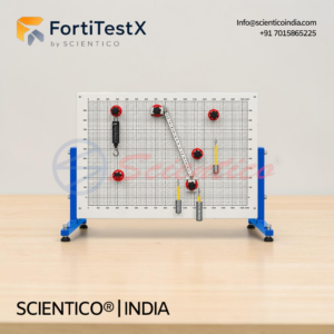
Equilibrium of a Rigid Body – FortiTestX – 51 is a demonstration kit designed for mechanics education using the Work Panel (FortiTestX 53). This hands-on apparatus allows students and teachers to explore equilibrium of a rigid body through experiments with an inclined ladder structure, measuring horizontal and vertical forces under various load conditions.
Product Overview
The kit consists of a model ladder that can be positioned at angles between 15 to 45 degrees, with or without a climbing mass at any position along its length. Magnetic components attach to the Work Panel (FortiTestX 53), enabling demonstrations of how equilibrium of a rigid body applies to real-world scenarios. The system includes spring balances to measure horizontal and vertical reaction forces, making it ideal for teaching structural safety and force distribution.
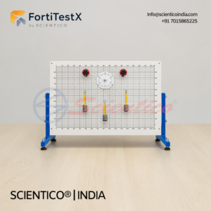
The Equilibrium of Forces FortiTestX – 50 is a kit for use with the Work Panel for experiments with three or more coplanar forces at equilibrium. This equilibrium of forces kit also introduces Bow’s notation. It fits directly onto the Work Panel for a complete range of statics experiments.
Product Overview
The Equilibrium of Forces FortiTestX – 50 is one of a series of kits for experiments in statics fundamentals topics. It fits to the Work Panel (FortiTextX 53) for a complete range of experiments that explore three or more coplanar forces in equilibrium.
Students or teachers fit the magnetic parts of the kit to the Work Panel (FortiTextX 53). This allows study or demonstration of three coplanar concurrent forces, known as a triangle of forces, or more, known as force polygons. The kit uses masses, hooks, pulleys and cords to apply forces on a single point (concurrent). Students may also set it to apply forces to two points (non-concurrent).
Students measure the forces at equilibrium and compare them with theoretical values. The equilibrium of forces kit introduces Bow’s notation and the drawing method of finding the forces. Up to five forces can be set at any angles, using its cords, rings, magnetic mounts, magnetic protractors, pulleys, weights and a spring balance.
A fully illustrated user guide is supplied with the kit, containing theory, experiments and typical results.
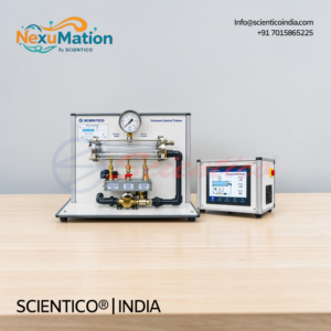
The Pressure Control Trainer NexuMation 70 contains an educational board with a pressurized vessel and a set of sensors and actuators for pressure. This pressure control trainer includes a control module with interface circuits and ON/OFF, proportional, integral and derivative (PID) control circuits.
Product Overview
The pressure control trainer contains an educational board with a pressurized vessel. A set of sensors and actuators for pressure is fitted on the board.
A control module contains the interface circuits for the sensors and the actuators. It also contains the ON/OFF and proportional integral and derivative control circuits (PID).
Sensors, control circuits, drivers, and protection circuits are installed. The user can control pressure of liquid manually or through a software PID control algorithm.
PID parameters are controllable and graph plotting is available.

The Pressure Control Training System NexuMation 69 offers a way to learn the basic fundamentals of control engineering. This pressure control training system charges a pressure tank with compressed air using a diaphragm gas pump. The experimental set-up is mounted on a housing which accommodates all the electronics.
Product Overview
The pressure control training system charges the pressure tank with compressed air by a diaphragm gas pump. A dial-gauge manometer allows the pressure in the tank to be observed directly at any time. The pressure is measured using a pressure sensor.
The sensor output signal is sent to the software controller. The output signal from the controller influences the speed of the diaphragm gas pump and hence the flow rate. An air consumer is simulated by way of a flow control valve. A solenoid valve, through which air can escape, can be activated by the software to investigate the influence of disturbance variables.
The powerful state-of-the-art software is an integral part of the training system and embodies the principle of hardware/software integration (HSI). It enables experiments to be conducted and evaluated in a user-friendly manner. The link between the experimental unit and the PC is made via a USB port.

The Temperature Control Trainer NexuMation 68 contains an educational board with a vessel and a set of sensors and actuators for temperature and flow. This temperature control trainer includes a control module with interface circuits and ON/OFF, proportional, integral and derivative (PID) control circuits.
Product Overview
The temperature control trainer contains an educational board with a vessel. A set of sensors and actuators for temperature and flow is fitted on the board.
A control module contains the interface circuits for the sensors and the actuators. It also contains the ON/OFF and proportional integral and derivative control circuits (PID).
Sensors, control circuits, drivers, and protection circuits are installed. The user can control pressure of liquid manually or through a software PID control algorithm.
PID parameters are controllable and graph plotting is available.
OUR MANUFACTURING FACILTY
SCIENTICO operates dedicated manufacturing units equipped with machining, fabrication, and assembly infrastructure for producing high-quality laboratory and engineering equipment.Our facility supports in-house production processes, ensuring precision, durability, and consistent performance across all product categories.
Real-time production and machining infrastructure at our facility
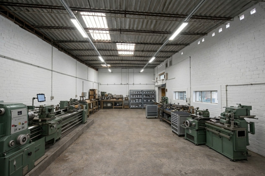
Machining & Fabrication Area
In-house machining setup equipped with precision tools for manufacturing engineering lab equipment components.
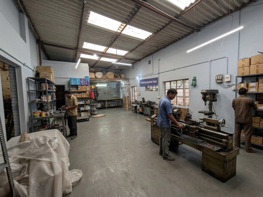
Lathe & Component Processing
Dedicated machining stations for accurate shaping and finishing of metal components.
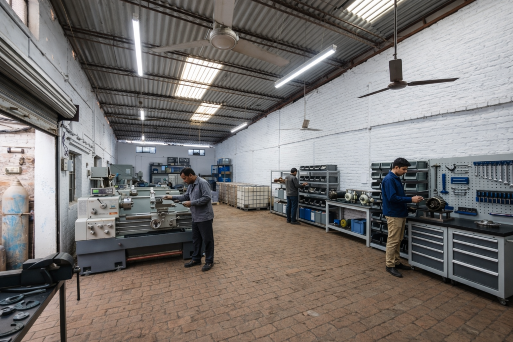
Assembly & Testing Area
Structured workspace for assembling and testing laboratory equipment before dispatch.
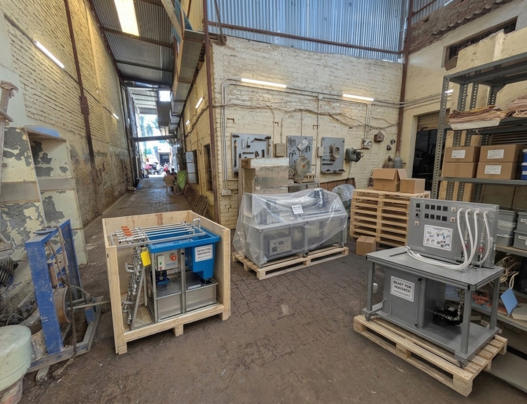
Storage & Pre-Dispatch Zone
Organized area for component storage and final inspection prior to shipment.
Need Assistance? We're Here to Help!
Start with a real buying task
Move from company research to a product or project brief
If you are evaluating Scientico as a manufacturer, the next useful step is to test the catalogue against one real requirement. Search an apparatus or model, review the specification, and send the quantity, destination and required documentation for a written response.
- Search one product or experiment.
- Review the product record and related equipment family.
- Add destination, quantity and tender requirements.
- Request a model-specific quotation or distributor discussion.