
Cavitation is the formation and subsequent violent collapse of vapour-filled bubbles in a flowing liquid when the local static pressure drops below the liquid’s saturation (vapour) pressure at the operating temperature. In pumps, turbines, valves, and propellers, these bubbles implode near solid surfaces, producing intense local pressure spikes that erode metal, generate noise and vibration, and degrade hydraulic performance.
Equipment mentioned in this guide
Review the product information, specifications and model before requesting a quotation.
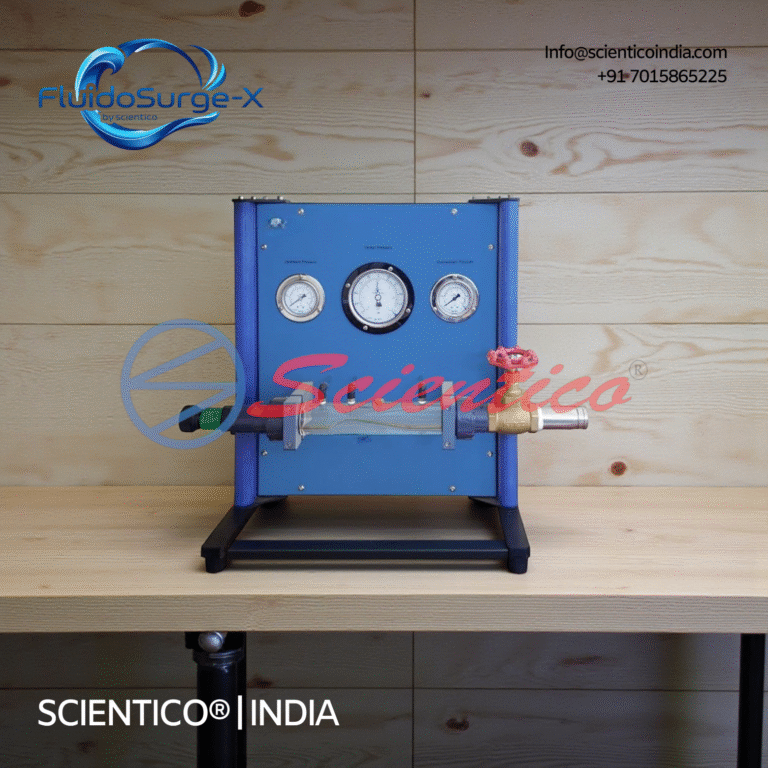
Cavitations Apparatus | FluidoSurge-X 184
The Cavitations Apparatus FluidoSurge-X 184 is designed to demonstrate the formation and effects of cavitation in flowing liquids. It enables clear visualization of vapor bubble formation and collapse within a Venturi section. The apparatus supports controlled variation of flow rate and pressure to reach cavitation conditions. It is suitable for fluid mechanics laboratory instruction and experimental analysis.
View product detailsWhat causes cavitation in pumps and turbines?
Cavitation begins whenever the absolute pressure at a point in the flow falls to the vapour pressure (pv) of the liquid. The liquid locally boils, forming vapour cavities; when the flow carries them into a higher-pressure region, they collapse almost instantaneously. The main triggers are:
- Low suction pressure, a pump installed too high above the sump, long suction lines, clogged strainers, or partially closed suction valves all reduce inlet pressure.
- High flow velocity, by Bernoulli’s principle, where velocity rises (impeller eye, runner blade tips, throttled valves), static pressure falls.
- High liquid temperature, vapour pressure rises sharply with temperature, so hot water cavitates more readily than cold.
- Operating off the best-efficiency point (BEP), recirculation at very low or very high flow creates localised low-pressure zones.
- High elevation / altitude, lower atmospheric pressure reduces the available suction head.
The governing parameter for pumps is Net Positive Suction Head (NPSH). Cavitation is avoided when the head available exceeds the head the pump requires:
NPSHavailable = (patm − pv) / (ρg) − Hs − hf > NPSHrequired
where patm is atmospheric pressure (Pa), pv is vapour pressure (Pa), ρ is liquid density (kg/m³), g = 9.81 m/s², Hs is static suction lift (m), and hf is friction head loss in the suction line (m). All NPSH terms carry units of metres of liquid column.
For turbines, the cavitation tendency is expressed through Thoma’s cavitation factor (σ):
σ = (Hatm − Hv − Hs) / H
where H is the net (working) head across the turbine. Cavitation is avoided when σ exceeds the critical cavitation factor σc for that machine.
What are the effects of cavitation?
The collapse of a single vapour bubble can generate transient local pressures of the order of hundreds of megapascals and micro-jets that strike the surface. The cumulative consequences include:
- Surface erosion (pitting), repeated implosions remove material, leaving a characteristic spongy, pitted surface on impeller vanes and runner blades.
- Noise and vibration, a distinctive “gravel” or crackling sound, often accompanied by shaft vibration that fatigues bearings and seals.
- Performance drop, vapour blocks flow passages, reducing developed head, discharge, and efficiency; severe cavitation causes a sudden head breakdown.
- Reduced service life, combined erosion, fatigue, and vibration shorten component life and raise maintenance cost.
How is cavitation prevented?
Prevention works by keeping the local pressure above vapour pressure throughout the flow path. Practical measures:
- Increase suction pressure, lower the pump relative to the liquid level, shorten and enlarge the suction pipe, and keep strainers clean to raise NPSHavailable.
- Reduce liquid temperature where the process allows, lowering pv.
- Operate near BEP, size pumps and turbines for their design duty and avoid prolonged throttled or low-flow running.
- Improve hydraulic design, use inducers ahead of impellers, smooth flow passages, and limit blade-tip velocities.
- Select cavitation-resistant materials, stainless steels, bronze, and Stellite-faced surfaces resist pitting.
- Set turbines correctly, install draft-tube and runner heights so σ > σc for the site head.
Cavitation in pumps vs turbines: a quick comparison
| Aspect | Pumps | Turbines |
|---|---|---|
| Where it occurs | Impeller eye / suction side (low-pressure inlet) | Runner blade exit and draft tube (low-pressure outlet) |
| Governing parameter | NPSH (NPSHa > NPSHr) | Thoma’s factor (σ > σc) |
| Primary cause | Insufficient suction head, high suction lift | Excessive draft head, off-design operation |
| Key fix | Lower pump / raise inlet pressure | Lower runner setting / correct draft-tube height |
| Common symptom | Head and discharge drop, noisy suction | Pitted runner, vibration, efficiency loss |
How do you select equipment to avoid cavitation?
When specifying a pump or turbine for a teaching lab or a field application, evaluate these selection criteria:
- NPSH margin, confirm NPSHavailable comfortably exceeds the manufacturer’s NPSHrequired (a margin of at least 0.5–1.0 m is typical).
- Operating range, match the duty point to the BEP, not the curve extremes.
- Liquid properties, account for temperature, vapour pressure, and any dissolved gases.
- Material specification, choose erosion-resistant alloys for high-duty or abrasive service.
- Instrumentation, for teaching rigs, ensure pressure tappings and gauges allow NPSH and σ to be computed from measured data.
What to ask a supplier: a checklist
- What is the NPSHrequired curve across the full operating range?
- At what flow is the best-efficiency point, and how wide is the safe operating band?
- What materials are used for the impeller / runner, and what is their cavitation-erosion resistance?
- Does the apparatus include pressure and flow instrumentation to demonstrate the onset of cavitation?
- Is a calibration certificate and an instruction/experiment manual supplied?
- What are the warranty, spares availability, and after-sales support terms?
- For export orders: what are the packing standards, lead time, and CIF quotation?
How is cavitation shown and measured in a teaching lab?
In an engineering fluid-mechanics laboratory, cavitation is demonstrated on a centrifugal-pump or turbine test rig fitted with calibrated suction and delivery pressure gauges and a flow meter. Students progressively throttle the suction valve (or raise the suction lift) while recording head, discharge, and inlet pressure. As NPSHavailable approaches NPSHrequired, the onset of cavitation is identified by:
- An audible crackling noise and increased vibration.
- A measurable drop in developed head and efficiency.
- The inlet pressure falling toward the water’s vapour pressure at the test temperature.
From the logged readings, students compute NPSHavailable for the pump or Thoma’s cavitation factor σ for the turbine, plot the head-breakdown curve, and compare the critical point against theory, reinforcing the link between Bernoulli’s equation, vapour pressure, and machine performance.
Scientico India manufactures and exports a wide range of ISO 9001:2015 and model-specific fluid-mechanics teaching apparatus for engineering colleges and universities in India and 30+ countries. Explore our Fluid Mechanics Lab Equipment to set up cavitation, NPSH, and turbine-performance experiments in your laboratory.
Frequently Asked Questions
What is cavitation in simple terms?
Cavitation is the formation of vapour bubbles in a liquid when local pressure drops below the liquid’s vapour pressure, followed by the violent collapse of those bubbles in higher-pressure regions. The implosions erode surfaces and cause noise, vibration, and loss of performance in pumps and turbines.
What is the difference between NPSH and Thoma’s cavitation factor?
NPSH (Net Positive Suction Head) is used for pumps and compares the suction head available against the head required; cavitation is avoided when NPSH-available exceeds NPSH-required. Thoma’s cavitation factor (sigma) is used for turbines and relates atmospheric, vapour, and suction heads to the net working head; cavitation is avoided when sigma exceeds the critical value.
How can cavitation be prevented in a centrifugal pump?
Keep the local pressure above vapour pressure by raising NPSH-available: lower the pump relative to the liquid level, shorten and enlarge the suction pipe, keep strainers clean, reduce liquid temperature, operate near the best-efficiency point, and select cavitation-resistant impeller materials.
Where does cavitation occur in a turbine?
In reaction turbines, cavitation typically occurs at the runner blade exit and in the draft tube, where pressure is lowest. It is controlled by setting the runner at the correct height so that Thoma’s cavitation factor stays above the critical value for the site head.
Cavitation and pump characteristics are studied experimentally on a centrifugal pump test rig across the head-discharge curve.
One honest ask
We don't gate anything on this site. You just read the whole thing free. If it was useful, leave your email and two things happen: we send you this page as a plain-text block you can paste into a tender file or an internal email, and we notify you the next time we publish a buyer tool like this one. Nothing else. No drip sequence, no sales calls booked without asking.