
Bernoulli’s principle states that within a steady, incompressible, frictionless flow, an increase in a fluid’s velocity occurs alongside a decrease in its pressure or potential energy. In other words, where a fluid moves faster, its static pressure drops. It is a direct expression of the conservation of energy applied to a moving fluid, derived by Swiss mathematician Daniel Bernoulli in 1738.
Equipment mentioned in this guide
Review the product information, specifications and model before requesting a quotation.
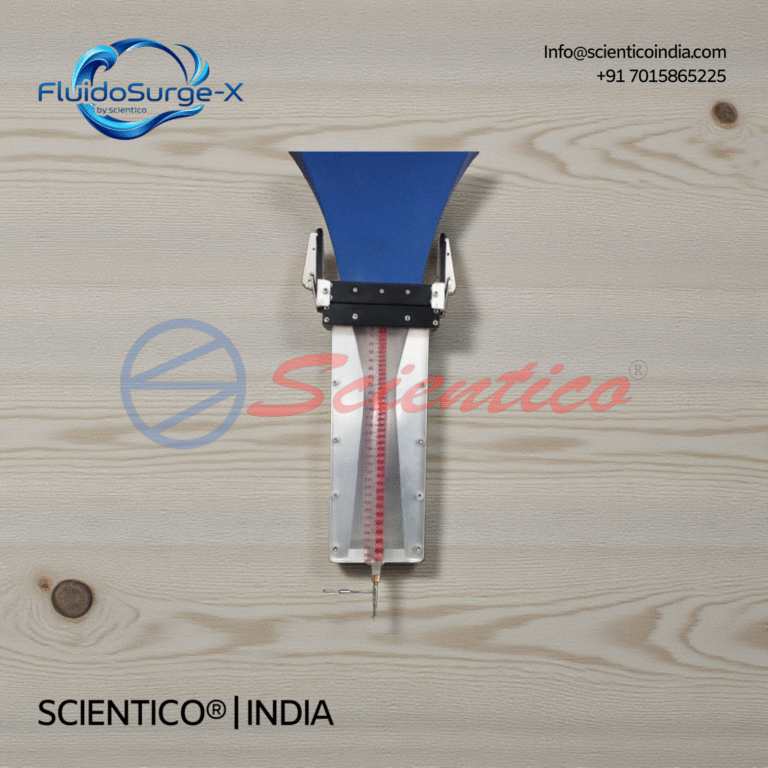
Bernoulli’s Principle Module | FluidoSurge-X 358
The Bernoulli’s Principle Module FluidoSurge-X 358 is a laboratory accessory designed to demonstrate the continuity equation and Bernoulli’s equation in steady airflow. Manufactured by SCIENTICO, this unit enables experimental measurement of static, dynamic, and total pressures within a variable cross-section duct. It is intended for use with the compatible Aerodynamics Trainer FluidoSurge-X 348.
View product details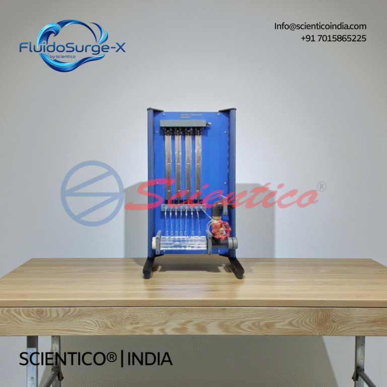
Bernoulli’s Theorem Apparatus | FluidoSurge-X 120
The Bernoulli's Theorem Apparatus FluidoSurge-X 120 is designed for experimental verification of Bernoulli’s principle in fluid mechanics laboratories. It enables detailed study of pressure, velocity, and energy variations along a converging and diverging duct. The apparatus uses a transparent Venturi test section with multiple pressure tapping points. It is intended for structured academic experiments and analytical comparison with theoretical flow behavior.
View product detailsWhat is the Bernoulli equation?
For steady, incompressible, inviscid flow along a streamline, the total mechanical energy per unit volume stays constant:
P + ½ρv² + ρgh = constant
Each term represents an energy contribution per unit volume (units: pascals, Pa = N/m² = J/m³):
- P, static pressure (Pa)
- ½ρv², dynamic pressure, where ρ is fluid density (kg/m³) and v is flow velocity (m/s)
- ρgh, hydrostatic (elevation) pressure, where g = 9.81 m/s² and h is height (m)
Dividing through by ρg expresses the same balance as head in metres: pressure head (P/ρg) + velocity head (v²/2g) + elevation head (h) = constant total head. This “head” form is what most teaching apparatus measures directly using manometer tubes.
What are the assumptions and limitations?
Bernoulli’s equation is an idealisation. It holds only when the following conditions are reasonably met:
- Steady flow, flow properties at any point do not change with time.
- Incompressible fluid, density is constant (valid for liquids and for gases below roughly Mach 0.3).
- Inviscid (frictionless) flow, viscous and turbulence losses are neglected.
- Flow along a single streamline, the constant differs between streamlines unless the flow is irrotational.
In real ducts, friction causes a measurable drop in total head between stations. This is why experimental readings never match the ideal exactly, quantifying that deviation is itself a core learning outcome.
What are the real-world applications of Bernoulli’s principle?
The principle underpins a large share of practical fluid and aerodynamic engineering. The table below maps common applications to the mechanism at work.
| Application | How Bernoulli’s principle applies |
|---|---|
| Venturi meter / flow nozzle | A constriction speeds up flow, lowering pressure; the pressure difference gives flow rate. |
| Pitot tube (aircraft airspeed) | Difference between stagnation and static pressure yields velocity from ½ρv². |
| Aerofoil / wing lift | Faster flow over the curved upper surface lowers pressure, contributing to lift. |
| Carburettor & spray atomisers | High-velocity air at a throat creates suction that draws and atomises fuel or liquid. |
| Chimney & ventilation draught | Wind across the top lowers pressure, inducing upward flow. |
How is the principle related to continuity?
Bernoulli’s equation is almost always paired with the continuity equation, which conserves mass:
A₁v₁ = A₂v₂ (for incompressible flow)
where A is cross-sectional area (m²) and v is velocity (m/s). When a pipe narrows, area falls, so velocity rises, and by Bernoulli, static pressure falls. Together these two equations let students predict pressure at any section of a converging-diverging duct and compare it against measured values.
How is Bernoulli’s principle demonstrated and measured in a teaching lab?
The standard instrument is a Bernoulli’s theorem apparatus: a horizontal converging-diverging (Venturi-shaped) transparent test section fitted with a row of vertical piezometer (manometer) tubes tapped at known cross-sections. Water is supplied from a constant-head tank and discharged into a measuring tank.
A typical procedure runs as follows:
- Establish steady flow and let the piezometer columns stabilise.
- Record the water-column height in each tube, this is the pressure head at that section.
- Measure the volumetric flow rate (Q) using the collecting tank and a stopwatch.
- Compute velocity at each section from v = Q/A using the known tube areas.
- Calculate velocity head (v²/2g) and add it to the measured pressure head to obtain total head at each section.
Students observe that pressure head falls at the throat (where area is smallest and velocity highest) and partially recovers downstream. The total head stays nearly constant along the duct, with a small decline that represents friction loss, verifying Bernoulli’s principle and exposing its limitations in one experiment.
How do you select a Bernoulli’s theorem apparatus?
For colleges and universities specifying equipment, key selection criteria include:
- Test-section material, clear acrylic or Perspex for visible flow and column readings.
- Number and spacing of piezometer tubes, more tapping points give a smoother head profile.
- Duct geometry, gradually converging-diverging section with documented area at each tapping.
- Flow supply, integral constant-head tank or compatibility with an existing hydraulic bench.
- Measuring tank & gauge, calibrated collecting tank with sight glass for accurate flow-rate timing.
- Frame and finish, corrosion-resistant stand suitable for a wet lab.
- Documentation, manual with theory, sample calculations, and a clear experiment procedure.
What should you ask a supplier?
Before placing an order, especially for export, confirm the following with the manufacturer:
- Are the exact cross-sectional areas at each piezometer tapping documented for calculation?
- Is the unit self-contained or does it require a separate hydraulic bench and pump?
- What is the range of flow rates and the rated supply head?
- Which quality certifications does the equipment and factory hold?
- What spares (tubes, seals, fittings) are available and what is the lead time?
- Is the apparatus supplied with a manual, calibration notes, and installation guidance?
- What are the packing, CIF terms, and delivery timeline to my port?
In summary, Bernoulli’s principle is the energy-conservation statement that links a fluid’s pressure, velocity, and elevation, and the converging-diverging Bernoulli apparatus makes it directly measurable by comparing pressure and velocity heads across a duct. Scientico India is an ISO 9001:2015 and model-specific manufacturer and exporter of engineering and science lab equipment, serving institutions across India and 30+ countries. Explore our full range of Fluid Mechanics Lab Equipment to equip your fluid mechanics laboratory.
Frequently Asked Questions
What does Bernoulli’s principle state in simple terms?
It states that in a steady, incompressible, frictionless flow, where a fluid moves faster its static pressure is lower, and where it moves slower its pressure is higher. It is the conservation of energy applied to a moving fluid.
What is the Bernoulli equation and its units?
The equation is P + ½ρv² + ρgh = constant along a streamline. Each term is an energy per unit volume measured in pascals (Pa = J/m³): P is static pressure, ½ρv² is dynamic pressure, and ρgh is elevation pressure.
What are the assumptions of Bernoulli’s principle?
It assumes steady flow, an incompressible fluid (constant density), inviscid or frictionless flow, and that the analysis follows a single streamline. Real flows include friction losses, so measured results deviate slightly from the ideal.
How is Bernoulli’s principle demonstrated in a lab?
Using a Bernoulli’s theorem apparatus: a transparent converging-diverging test section with piezometer tubes. Students read pressure heads at each section, measure flow rate, compute velocity heads, and verify that total head stays nearly constant while pressure falls at the throat.
What is the difference between Bernoulli’s equation and the continuity equation?
The continuity equation (A₁v₁ = A₂v₂) conserves mass and shows that a smaller area means higher velocity. Bernoulli’s equation conserves energy and shows that higher velocity means lower pressure. They are used together to analyse flow through varying-area ducts.
The principle is verified in the lab on a Bernoulli’s theorem apparatus by measuring piezometric head along a converging-diverging duct.
One honest ask
We don't gate anything on this site. You just read the whole thing free. If it was useful, leave your email and two things happen: we send you this page as a plain-text block you can paste into a tender file or an internal email, and we notify you the next time we publish a buyer tool like this one. Nothing else. No drip sequence, no sales calls booked without asking.