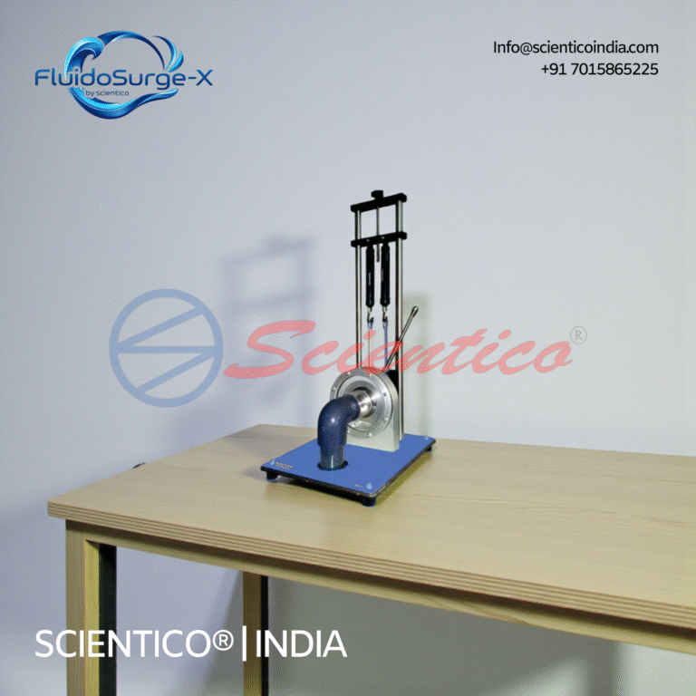
The Kaplan Turbine Apparatus FluidoSurgeX 208 is a laboratory-scale training system designed to study the operating characteristics of a Kaplan reaction turbine. Manufactured by SCIENTICO, the apparatus demonstrates energy conversion from hydraulic power to mechanical power. It is suitable for instructional experiments in fluid mechanics and hydraulic machinery laboratories. The system operates using a controlled water supply from a hydraulic bench.
A Kaplan Turbine is an axial-flow reaction turbine with adjustable runner blades and adjustable guide vanes (wicket gates). It is designed for low-head, high-flow applications such as tidal barrages, run-of-river plants, and large canal headworks. The adjustable blades allow the turbine to operate efficiently across a wide range of flow rates and water heads, unlike Francis or Pelton turbines, which have fixed-point peak efficiency.
The Kaplan Turbine Test Rig manufactured by Scientico India is a laboratory-scale apparatus used by engineering colleges to study the performance characteristics, efficiency curves, and unit speed/power/discharge relationships of axial-flow turbines.
Kaplan Turbine vs Francis vs Pelton: Quick Comparison
Parameter
Kaplan Turbine
Francis Turbine
Pelton Turbine
Type
Axial-flow, reaction
Mixed-flow, reaction
Impulse
Head range
2–40 m (low head)
40–600 m (medium)
300–1800 m (high)
Flow
Very high
Medium–high
Low–medium
Runner blades
Adjustable
Fixed
Fixed (buckets)
Efficiency (peak)
90–95%
85–92%
88–92%
Applications
Tidal, run-of-river
Dams, reservoirs
Mountain streams, penstocks
Kaplan Turbine Test Rig Experiment: Objective
Determine the characteristic curves (performance curves) of a Kaplan turbine at constant head.
Plot unit speed (N_u), unit discharge (Q_u), and unit power (P_u) vs guide vane opening.
Determine the efficiency of the turbine at various operating points.
Find the runaway speed and shutoff head.
Theory: Performance Parameters of Kaplan Turbine
Unit Speed (N_u): N_u = N / √H Unit Discharge (Q_u): Q_u = Q / (D² √H) Unit Power (P_u): P_u = P / (D² H^(3/2)) Overall Efficiency (η): η = P_shaft / (ρgQH) Where: N = speed (rpm), H = net head (m), Q = flow rate (m³/s), D = runner diameter (m), P = shaft power (W).
Kaplan Turbine Experiment Procedure
Apparatus Required
Kaplan Turbine Test Rig (Scientico, closed-loop, with sump tank and pump)
Differential pressure gauge / manometer for head measurement
Flow meter (electromagnetic or venture meter in supply pipe)
Tachometer (digital, non-contact)
Rope brake dynamometer or torque sensor for power measurement
Spring balance and weight pan (for rope brake)
Step-by-Step Procedure
Fill the sump tank. Prime the supply pump. Open all inlet valves.
Set guide vane opening to a fixed position (e.g., 50% open). Set runner blade pitch angle.
Start the supply pump. Allow flow to stabilise. Record inlet head H₁ and outlet head H₂ from pressure gauges.
Calculate net head: H = H₁ − H₂ + (V₁² − V₂²)/2g (velocity head correction).
Record flow rate Q from the flow meter.
Record turbine speed N (rpm) from the tachometer.
Apply rope brake load: add dead weights to the weight pan. Record spring balance reading S (N) and weight W (N). Torque T = (W − S) × R, where R = radius of brake drum + half of rope diameter.
Calculate shaft power: P = 2πNT/60 (W).
Calculate water power: P_w = ρgQH.
Calculate efficiency: η = P / P_w × 100%.
Repeat for different guide vane openings (25%, 50%, 75%, 100%) and different brake loads at each opening.
Observations Table
Guide Vane Opening (%)
Head H (m)
Flow Q (m³/s)
Speed N (rpm)
Torque T (Nm)
Shaft Power P (W)
Water Power P_w (W)
Efficiency η (%)
25%
50%
75%
100%
Graphs to Plot
η vs N (efficiency vs speed at constant head)
Q vs N (flow rate vs speed)
P vs N (power vs speed)
η vs P (efficiency vs power, the efficiency hill chart)
Unit speed N_u vs unit discharge Q_u (universal characteristic)
Result and Discussion
Report the maximum efficiency achieved and the operating point (N, Q, H) at which it occurs. Compare the peak efficiency with the theoretical design efficiency. Discuss the effect of guide vane opening on flow rate, speed, and efficiency. Explain the advantage of adjustable runner blades in maintaining efficiency at off-design flow conditions.
Viva Questions: Kaplan Turbine Experiment
What is the main advantage of adjustable runner blades in a Kaplan turbine?
How does a Kaplan turbine differ from a Francis turbine in flow direction?
What is unit speed and why is it used instead of actual speed for turbine characteristics?
Define runaway speed and explain its significance in turbine design.
What is draft tube and what is its function in a Kaplan turbine installation?
What is specific speed and how does it classify turbine types?
Why is Kaplan turbine preferred over Francis at very low heads?
Kaplan Turbine Test Rig Manufacturer India
Scientico India manufactures Kaplan Turbine Test Rigs for fluid mechanics and hydraulic machinery labs in engineering colleges. The closed-loop rig includes adjustable guide vanes, adjustable runner blade pitch, rope brake dynamometer, electromagnetic flow meter, digital tachometer, and complete manuals with observation tables. model-specific and ISO 9001:2015 manufactured. Exported to UAE, Saudi Arabia, Kenya, Bangladesh, Sri Lanka, Philippines, Vietnam, and Nepal. Request a CIF quotation.
Need lab equipment for your institution?
Manufacturer of laboratory training equipment since 1993. Request pricing, technical information and an international quotation.
{“@context”:”https://schema.org”,”@type”:”HowTo”,”name”:”Kaplan Turbine Test Rig Experiment, Efficiency and Performance”,”description”:”Procedure to determine the performance characteristics (efficiency, power output, specific speed) of a Kaplan (axial flow) turbine.”,”totalTime”:”PT2H30M”,”step”:[{“@type”:”HowToStep”,”position”:1,”name”:”Setup”,”text”:”Open the inlet valve to fill the spiral casing. Check all pressure gauges at inlet and draft tube. Set the runner blade angle and guide vane angle to initial positions.”},{“@type”:”HowToStep”,”position”:2,”name”:”Set Head”,”text”:”Adjust the supply valve to achieve the design head H (as specified on the turbine nameplate, typically 2-5 m for lab-scale units). Record the head from inlet pressure gauge and tail water level.”},{“@type”:”HowToStep”,”position”:3,”name”:”Start the Turbine”,”text”:”Open the guide vanes to allow flow. The runner begins rotating. Allow 2-3 minutes for steady-state conditions before recording.”},{“@type”:”HowToStep”,”position”:4,”name”:”Measure Power Output”,”text”:”Apply load to the brake drum dynamometer. Record: load (W), spring balance reading (S), and braking radius (R). Shaft power Ps = (W-S) × R × 2πN/60, where N = RPM.”},{“@type”:”HowToStep”,”position”:5,”name”:”Measure Flow Rate”,”text”:”Calculate flow rate Q from the differential pressure across the venturimeter or from the V-notch/rectangular weir in the tail channel.”},{“@type”:”HowToStep”,”position”:6,”name”:”Calculate Efficiency”,”text”:”Water power Pi = ρgQH. Mechanical efficiency η = Ps/Pi × 100%. Repeat at 5-7 different guide vane openings.”},{“@type”:”HowToStep”,”position”:7,”name”:”Vary Runner Blade Angle”,”text”:”Change the runner blade pitch angle and repeat measurements. Plot efficiency vs flow rate for each blade angle to find the optimal setting, this demonstrates the Kaplan turbine’s advantage of double regulation.”}]}
Get Specifications & Pricing
Scientico India manufactures laboratory apparatus under an ISO 9001:2015 quality system. Conformity documentation is confirmed for each quoted model. Contact us for full specifications, pricing, and documentation.
Looking to set up this experiment? Scientico India manufactures and exports model-specific Pelton and Kaplan Turbine Test Rigs to engineering colleges in UAE, Saudi Arabia, Kenya, Bangladesh, Philippines, and 30+ countries. Email [email protected] for a proforma invoice within 24 hours.
Need this apparatus for your lab?
Scientico India manufactures this and the full range of Fluid Mechanics Lab equipment, model-specific and supplied to engineering colleges worldwide.
We don't gate anything on this site. You just read the whole thing free. If it was useful, leave your email and two things happen: we send you this page as a plain-text block you can paste into a tender file or an internal email, and we notify you the next time we publish a buyer tool like this one. Nothing else. No drip sequence, no sales calls booked without asking.
Laboratory and engineering training equipment for institutions, distributors and procurement teams. Request a quotation for your model, quantity and destination.