
Equipment mentioned in this guide
Review the product information, specifications and model before requesting a quotation.
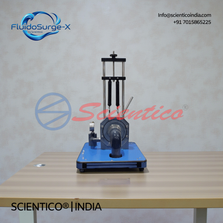
Francis Turbine Apparatus | FluidoSurge-X 160
The Francis Turbine Apparatus FluidoSurge-X 160 is designed to demonstrate the working principle and performance characteristics of a reaction turbine. It enables experimental study of pressure energy conversion, torque generation, and efficiency under controlled flow conditions. The apparatus operates with a hydraulic bench or laboratory water supply. It is suitable for hydraulic machinery and fluid mechanics laboratory instruction.
View product detailsFrancis Turbine Test Rig Experiment: Procedure, Calculations, and Performance Curves
The Francis turbine experiment demonstrates the operation of a mixed-flow reaction turbine, the most widely installed turbine type in the world for medium-head hydroelectric power. Students measure turbine efficiency, output power, and speed under varying load conditions, plotting characteristic curves. This guide covers theory, apparatus, procedure, observation table, and calculations for engineering laboratory use.
Theory: Francis Turbine Operating Principle
The Francis turbine is a reaction turbine, water enters the runner under both pressure and velocity. Unlike the Pelton wheel (impulse), pressure drops across the runner as energy is extracted. Water enters radially through guide vanes (wicket gates) and exits axially through the draft tube.
Specific speed: Ns = N√P / H^(5/4), Francis turbines operate at Ns = 60–300
Output power: P = 2πNT/60 (W)
Input water power: P_in = ρgQH (W)
Overall efficiency: η = P/P_in × 100%
Apparatus Description
- Francis turbine runner (mixed-flow, radial-axial) with adjustable guide vanes
- Spiral casing (volute) for uniform water distribution to guide vanes
- Draft tube for pressure recovery at runner exit
- Rope brake dynamometer for mechanical load measurement
- Pressure gauges at inlet and outlet for net head measurement
- Flow measurement by venturi meter or electromagnetic flowmeter
- Digital tachometer for speed measurement
- Centrifugal pump + sump for water recirculation
Experimental Procedure
Setup and No-Load Reading
- Start the pump and fully open the guide vanes, measure inlet pressure P₁ and outlet P₂
- Calculate net head: H = (P₁ – P₂)/ρg + (V₁² – V₂²)/2g
- Measure flow rate Q using the venturi meter or rotameter
- Record no-load speed N₀ (rpm) at the given head
Load Test (Constant Head)
- Apply rope brake load in steps (add weights W in increments)
- At each load: record N (rpm), W (N), spring balance S (N)
- Calculate torque: T = (W – S) × r_drum
- Calculate output power: P_out = 2πNT/60
- Calculate efficiency: η = P_out / (ρgQH) × 100%
- Continue until speed drops to ~50% of no-load speed
Observation Table
| Run | N (rpm) | W (N) | S (N) | T (N·m) | P_out (W) | Q (m³/s) | H (m) | η (%) |
|---|---|---|---|---|---|---|---|---|
| No load | 0 | 0 | 0 | 0 | 0 | |||
| 1 | ||||||||
| 2 | ||||||||
| 3 | ||||||||
| 4 |
Graphs to Plot
- Speed N vs. Torque T
- Speed N vs. Output Power P_out (shows maximum power speed)
- Speed N vs. Efficiency η (shows maximum efficiency speed)
- Unit power P₁₁ vs. unit speed N₁₁ (dimensionless characteristic curve)
Expected Results
- Maximum efficiency: 75–88% (lab rig scale losses are higher than full-scale turbines)
- Maximum efficiency occurs at approximately 70–80% of no-load speed
- Torque is maximum at zero/low speed (stall); power peaks at an intermediate speed
Viva Questions
- What is the difference between an impulse and a reaction turbine?
- Why does the Francis turbine use a draft tube?
- Define specific speed. At what specific speed does the Francis turbine operate?
- How do the guide vane openings affect turbine speed and efficiency?
- Compare Francis, Pelton, and Kaplan turbines for head and flow conditions
Get a Quote
Scientico India exports model-specific Francis Turbine Test Rigs to engineering colleges in UAE, Saudi Arabia, Kenya, Bangladesh, Philippines, and 30+ countries. Contact [email protected] for a proforma invoice within 24 hours.
{“@context”:”https://schema.org”,”@type”:”HowTo”,”name”:”Francis Turbine Experiment, Efficiency and Performance Analysis”,”description”:”Procedure to determine the hydraulic efficiency, mechanical efficiency, and overall efficiency of a Francis (mixed-flow) turbine.”,”totalTime”:”PT2H30M”,”step”:[{“@type”:”HowToStep”,”position”:1,”name”:”Pre-operation Check”,”text”:”Check the Francis turbine test rig: verify spiral casing inlet pressure gauge, draft tube outlet, guide vane mechanism, and dynamometer are all functional. Fill the header tank or ensure pump is primed.”},{“@type”:”HowToStep”,”position”:2,”name”:”Set Guide Vane Opening”,”text”:”Set the guide vane angle to the design position (typically 70-80% of full opening for initial test). Record the guide vane angle setting.”},{“@type”:”HowToStep”,”position”:3,”name”:”Establish Flow”,”text”:”Open the main supply valve gradually. Record the inlet pressure head H₁ (at spiral casing inlet) and draft tube pressure head H₂. Net head: Hn = H₁ – H₂.”},{“@type”:”HowToStep”,”position”:4,”name”:”Measure Flow Rate”,”text”:”Determine flow rate Q from venturimeter or calibrated orifice at the inlet pipeline. Record differential pressure and calculate Q using the venturimeter equation.”},{“@type”:”HowToStep”,”position”:5,”name”:”Load the Turbine”,”text”:”Apply braking torque using the dynamometer. Record: load (W), spring balance reading (S), brake drum radius (R), and rotational speed N (RPM). Calculate shaft power: Ps = (W-S) × R × 2πN/60.”},{“@type”:”HowToStep”,”position”:6,”name”:”Calculate Efficiencies”,”text”:”Water power: Pi = ρgQH. Overall efficiency: η_overall = Ps/Pi. Calculate unit speed: N₁₁ = N/√H. Unit discharge: Q₁₁ = Q/D²√H. These allow comparison across different heads.”},{“@type”:”HowToStep”,”position”:7,”name”:”Vary Guide Vane Opening”,”text”:”Change guide vane opening to 50%, 60%, 90% positions. Repeat measurements at each setting. Plot efficiency curves (η vs Q and η vs N₁₁). Identify best efficiency point (BEP). Typical Francis turbine η: 85-93% at BEP.”}]}Get Specifications & Pricing
Scientico India manufactures laboratory apparatus under an ISO 9001:2015 quality system. Conformity documentation is confirmed for each quoted model. Contact us for full specifications, pricing, and documentation.
WhatsApp: +91 701-586-5225 | [email protected] | FAQ, Shipping, Payment & Warranty
Scientico India manufactures this and the full range of Fluid Mechanics Lab equipment, model-specific and supplied to engineering colleges worldwide.
Explore Fluid Mechanics Lab Equipment → or request a quoteOne honest ask
We don't gate anything on this site. You just read the whole thing free. If it was useful, leave your email and two things happen: we send you this page as a plain-text block you can paste into a tender file or an internal email, and we notify you the next time we publish a buyer tool like this one. Nothing else. No drip sequence, no sales calls booked without asking.