Electro-Hydraulic Training System | MX-05
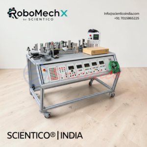
The Electro-Hydraulic Training System MX-05 teaches electro-hydraulic control through hands-on circuits. This electro-hydraulic training system includes a power unit, cylinders, solenoid valves, relays, and sensors on a mobile frame. Optional simulation software supports circuit design and troubleshooting.
The Electro-Hydraulic Training System MX-05 is a hands-on trainer for learning how electrical and hydraulic control systems work together. This electro-hydraulic training system covers solenoid valves, relays, limit switches, and basic to advanced circuit design.
Product Overview
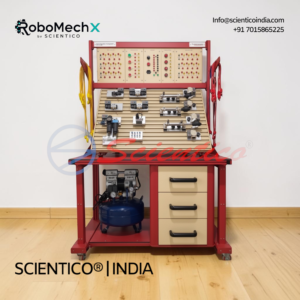
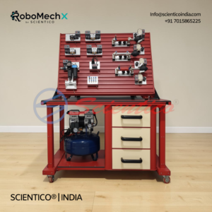
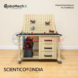
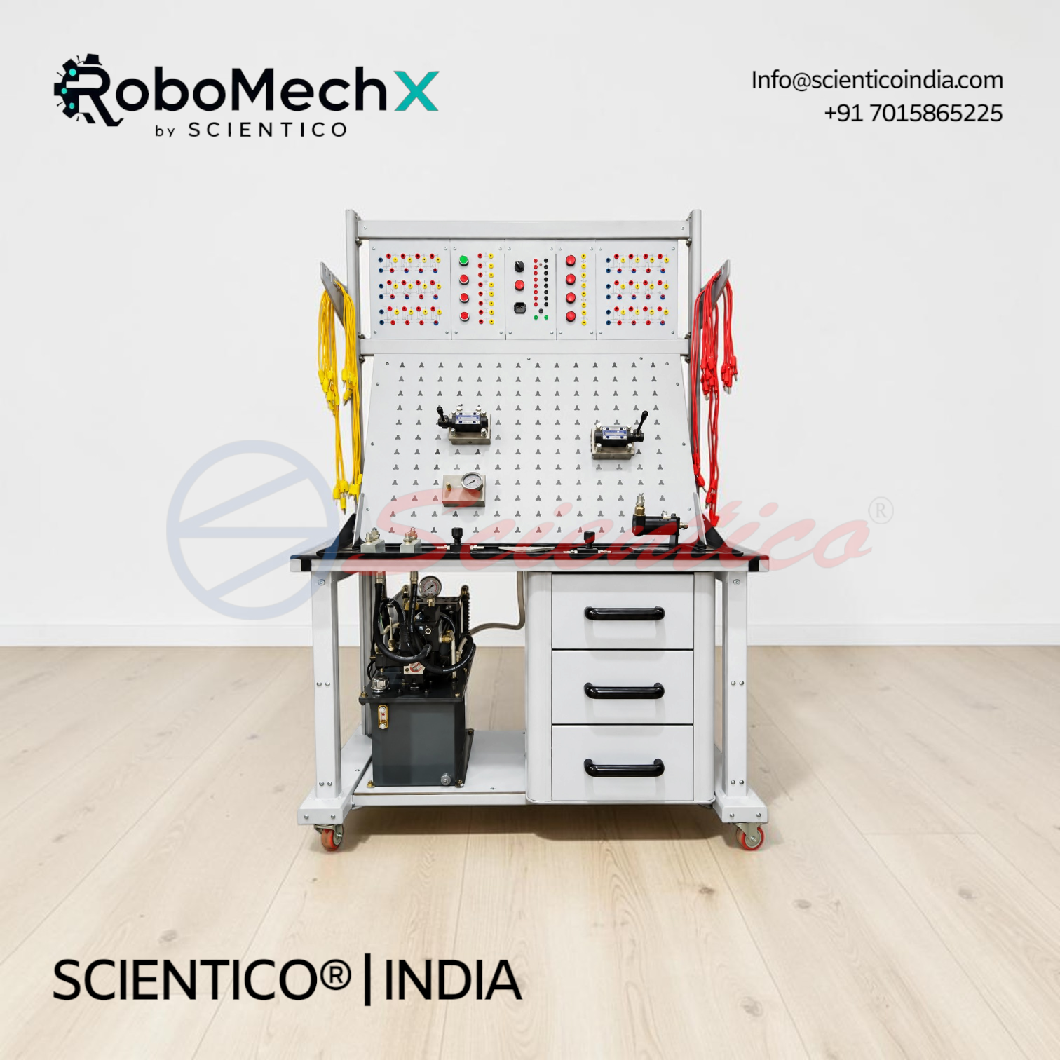
The MX-05 electro-hydraulic training system is a sturdy, self-explanatory trainer on a frame with caster wheels. It includes a power unit, cylinders, a hydraulic motor, valves, pressure gauges, and an accumulator. Electrical modules include push buttons, relays, a digital time relay, limit switches, and inductive, capacitive, and optical sensors. Inbuilt safety measures and leakage protection are provided. Optional simulation software supports circuit design and troubleshooting.
Electro-Hydraulic Training System MX-05 — Technical Specifications
| Parameter | Value |
|---|---|
| Power Unit | 1 pump with table |
| Double Acting Cylinders | 2 (standard and transparent) |
| Hydraulic Motor | 1 |
| Accumulator | 1 |
| Hoses | 1500 mm (2), 1000 mm (6), 600 mm (12) |
| Pressure Relief Valves | 2 directly actuated |
| Pressure Gauges | 6 (3 standard, 3 with distributor) |
| Solenoid Valves | 3/2-way, 4/2-way, 4/2-way double, two 4/3-way double |
| Electrical Sensors | Inductive, capacitive, optical |
| Limit Switches | 4 (2 left, 2 right) |
| Relay Units | 2 (3-fold each) |
| Digital Time Relay | 1 |
| Power Supply | 1 |
| Frame | Sturdy, with caster wheels |
Technical Data
Hydraulic Section:
- Power unit with pump and table
- Double acting cylinder and transparent double acting cylinder
- Hydraulic motor
- Flow measuring unit and weight
- Pressure relief valves (directly actuated, 2 units)
- One-way and pressure-compensated flow control valves
- Check valves (1 bar, 3 units) and pilot-actuated check valve
- Accumulator and pressure remover
- Hydraulic hose hanger
Electrical Section:
- Push button switch set (3-fold)
- Pilot lamp and buzzer unit
- Relay units (3-fold, 2 units)
- Digital time relay
- Pressure switch
- Electric limit switches (left and right)
- Inductive, capacitive, and optical sensors
Power supply and cable set
Hydraulic Modules
- Oil Tray, qty 1
- Power Unit with Pump and Table, qty 1
- Flow Measuring Unit, qty 1
- Weight, qty 1
- Double Acting Cylinder, qty 1
- Hydraulic Motor, qty 1
- Transparent Double Acting Cylinder, qty 1
- Pressure Relief Valve, directly actuated, qty 2
- One-Way Flow Control Valve, qty 1
- Pressure-Compensated Flow Control Valve, qty 1
- Check Valve, 1 bar, qty 3
- Pilot-Actuated Check Valve, qty 1
- Pressure Gauge, qty 3
- Pressure Gauge with Distributor, qty 3
- T Connectors, qty 4
- Accumulator, qty 1
- Hose 1500 mm, qty 2
- Hose 1000 mm, qty 6
- Hose 600 mm, qty 12
- Hydraulic Hose Hanger, qty 1
- Pressure Remover, qty 1
Electrical and Electro-Hydraulic Modules
- 3/2-Way Solenoid Valve, qty 1
- 4/2-Way Solenoid Valve, qty 1
- 4/2-Way Double Solenoid Valve, qty 1
- 4/3-Way Double Solenoid Valve, PABT Connected, qty 1
- 4/3-Way Double Solenoid Valve, PT Connected, qty 1
- Power Supply, qty 1
- Pressure Switch, qty 1
- Push Button Switch Set, 3-fold, qty 1
- Pilot Lamp and Buzzer Unit, qty 1
- Relay Unit, 3-fold, qty 2
- Digital Time Relay, qty 1
- Electric Limit Switch, Left, qty 2
- Electric Limit Switch, Right, qty 2
- Inductive Sensor, qty 1
- Capacitive Sensor, qty 1
- Optical Sensor, qty 1
- Cable Set, qty 1
Key Features
- Sturdy Design: Robust frame with caster wheel arrangement for mobility
- Self-Explanatory System: Clear layout for learning electro-hydraulic principles
- Inbuilt Safety: Safety measures and protection against leakage
- Mixed Technology Training: Electrical and hydraulic control in one system
- Sensor Integration: Inductive, capacitive, and optical sensors for signal detection
- Simulation Support: Optional software for circuit design and fault simulation
Experiments
- Function of electrical push button and limit switches
- Function and use of hydraulic solenoid valves
- Design and operation of a relay
- Reading electrical and hydraulic diagrams
- Design, construction, and operation of basic circuits
- Selecting solenoid valves for control requirements
- Basic logic functions
- Direct and indirect control of actuators
- Electric latching circuits
- Electrical signal locking in relay control systems
- Manual and automatic operation
- Interlocking circuits
- Rapid traverse circuit
- Pressure switch operation
Construction and Design
The MX-05 system is mounted on a sturdy frame with caster wheels. The hydraulic section includes a power unit, cylinders, a motor, valves, and an accumulator, connected by hoses of 600 mm, 1000 mm, and 1500 mm. The electrical section includes switches, relays, sensors, and a digital time relay. Hose hangers and a cable set keep the setup organised during use.
Software
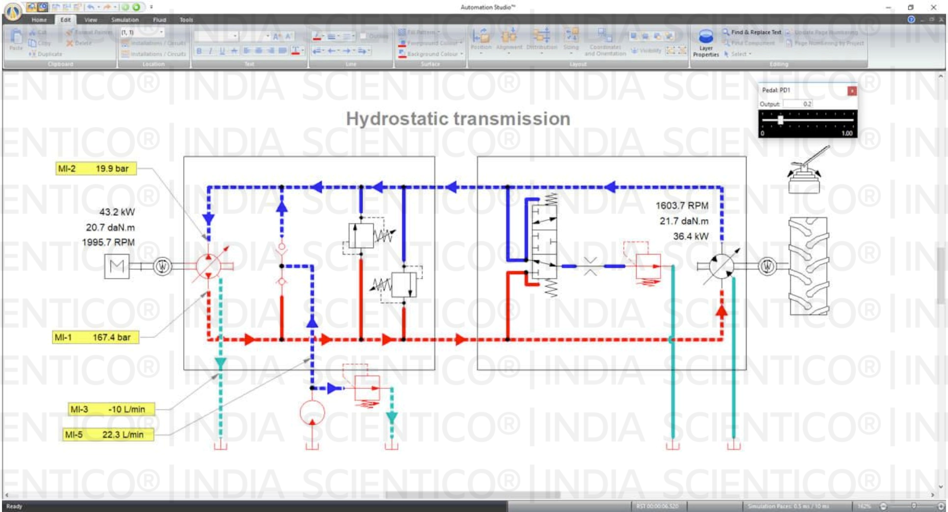
Optional simulation software with an ISO 1219-1 and ISO 1219-2 compliant hydraulic library. It allows users to:
- Create, simulate, and troubleshoot hydraulic and electro-hydraulic circuits
- Adjust component parameters, loads, leaks, viscosity, and thermal characteristics
- Build custom libraries and cut-away circuits showing flow in each component
- Create digital twins of the hardware trainer
- Activate component failures manually or by preset conditions
- Plot simulation data live
Scope of Delivery
- 1 Oil tray
- 1 Power unit with pump and table
- 1 Flow measuring unit
- 1 Weight
- 1 Double acting cylinder
- 1 Hydraulic motor
- 1 Transparent double acting cylinder
- 2 Pressure relief valves (directly actuated)
- 1 One-way flow control valve
- 1 Pressure-compensated flow control valve
- 3 Check valves (1 bar)
- 1 Pilot-actuated check valve
- 3 Pressure gauges
- 3 Pressure gauges with distributor
- 4 T connectors
- 1 Accumulator
- 2 Hoses (1500 mm)
- 6 Hoses (1000 mm)
- 12 Hoses (600 mm)
- 1 Hydraulic hose hanger
- 1 Pressure remover
- 1 3/2-way solenoid valve
- 1 4/2-way solenoid valve
- 1 4/2-way double solenoid valve
- 1 4/3-way double solenoid valve (PABT connected)
- 1 4/3-way double solenoid valve (PT connected)
- 1 Power supply
- 1 Pressure switch
- 1 Push button switch set (3-fold)
- 1 Pilot lamp and buzzer unit
- 2 Relay units (3-fold)
- 1 Digital time relay
- 2 Electric limit switches (left)
- 2 Electric limit switches (right)
- 1 Inductive sensor
- 1 Capacitive sensor
- 1 Optical sensor
- 1 Cable set
Q: What does the Electro-Hydraulic Training System MX-05 teach?
A: It teaches how electrical and hydraulic components interact in control circuits, including solenoid valves, relays, sensors, and actuators.
Q: Does the MX-05 include simulation software?
A: Simulation software is available as an optional add-on. It supports circuit design, fault simulation, and digital twin creation.
Q: Which sensors are included with the MX-05?
A: The system includes inductive, capacitive, and optical sensors, along with electric limit switches and a pressure switch.
Q: Is the MX-05 easy to move in a classroom?
A: Yes. The system frame has a caster wheel arrangement.
Need Assistance? We're Here to Help!
Connect with our team for product specifications, pricing, and customized solutions for your institution or project.