Exhaust Gas Calorimeter | ThermoFlux – 7105
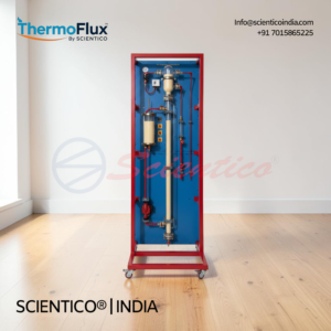
Exhaust Gas Calorimeter ThermoFlux – 7105 is a laboratory apparatus for determining thermal exhaust gas losses of internal combustion engines using the exhaust gas calorimeter method of calorimetric measurement.
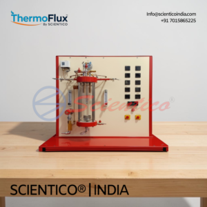
The unit consists of an insulated stainless steel tank with an internal looped finned pipe heat exchanger. Exhaust gas flows from bottom to top through the tank, transferring heat to cooling water circulating through the finned pipe. Heat exchange area on the exhaust gas side is 1.169 m²; on the water side, 0.164 m².
Four temperature sensors record exhaust gas and water inlet and outlet temperatures (-100 to 400°C each pair). A flow meter records water flow rate (4 to 36 LPM). All values are recorded electronically and displayed digitally via a measuring amplifier. The engine connects to the unit via an exhaust gas hose. Specific heat capacity of the exhaust gas can also be determined.
Supplied by SCIENTICO India with an instructional manual.
The Exhaust Gas Calorimeter ThermoFlux – 7105 is a laboratory apparatus for determining the thermal exhaust gas losses of internal combustion engines using calorimetric measurement. The exhaust gas calorimeter achieves largely complete and loss-free heat exchange between the exhaust gas and a cooling water circuit, enabling accurate calculation of the engine energy balance.
The unit consists of an insulated stainless steel tank through which exhaust gas flows from bottom to top, transferring its heat to a looped finned pipe heat exchanger carrying cooling water. Four temperature sensors and a flow meter record all relevant parameters; values are displayed digitally via a measuring amplifier.
Product Overview
The Exhaust Gas Calorimeter ThermoFlux – 7105 determines the amount of heat contained in the exhaust gas from test engines. The calorimeter consists of a finned pipe heat exchanger housed in an insulated stainless steel tank. Exhaust gas enters at the bottom of the tank and flows upward, giving up its heat almost completely to cooling water circulating through the finned pipe.
The finned pipe is arranged in loops to maximise the heat exchange area. The heat exchange area on the exhaust gas side is 1.169 m². The heat exchange area on the water side is 0.164 m². This large ratio ensures thorough and near-complete heat transfer from the exhaust gas to the cooling medium, which is the core operating principle of the exhaust gas calorimeter.
Four temperature sensors record exhaust gas inlet and outlet temperatures and water inlet and outlet temperatures. A flow meter records the cooling water flow rate. All measured values are recorded electronically and displayed digitally using a measuring amplifier. The engine is connected to the calorimeter via an exhaust gas hose. The specific heat capacity of the exhaust gas can also be determined from the recorded data.
Exhaust Gas Calorimeter ThermoFlux – 7105: Technical Specifications
| Parameter | Value |
|---|---|
| Apparatus Type | Exhaust gas calorimeter with finned pipe heat exchanger and insulated tank |
| Tank Construction | Insulated, stainless steel |
| Exhaust Gas Flow Direction | Bottom to top through the tank |
| Heat Exchanger Type | Finned pipe, arranged in loops |
| Heat Exchange Area: Exhaust Gas Side | 1.169 m² |
| Heat Exchange Area: Water Side | 0.164 m² |
| Temperature Sensors | 4 x sensors (exhaust gas inlet/outlet, water inlet/outlet) |
| Exhaust Gas Temperature Range | 2 x -100 to 400°C |
| Water Temperature Range | 2 x -100 to 400°C |
| Flow Rate Measurement Range | 4 to 36 LPM |
| Instrumentation | 4 temperature sensors, flow meter, measuring amplifier with digital display |
| Engine Connection | Exhaust gas hose |
| Data Recording | Electronic; digital display via measuring amplifier |
Technical Data
Calorimeter
| Parameter | Value |
|---|---|
| Construction | Insulated, stainless steel |
| Heat Exchanger Type | Finned pipe heat exchanger |
| Heat Exchange Area: Exhaust Gas Side | 1.169 m² |
| Heat Exchange Area: Water Side | 0.164 m² |
Measuring Ranges
| Parameter | Range |
|---|---|
| Exhaust Gas Temperature | 2 x -100 to 400°C |
| Water Temperature | 2 x -100 to 400°C |
| Flow Rate | 4 to 36 LPM |
Key Features
- Apparatus Type: exhaust gas calorimeter for internal combustion engine thermal loss determination
- Tank Construction: insulated, stainless steel
- Exhaust Gas Flow Direction: bottom to top through the insulated tank
- Heat Exchanger: finned pipe arranged in loops for maximum heat exchange area
- Heat Exchange Area: Exhaust Gas Side: 1.169 m²
- Heat Exchange Area: Water Side: 0.164 m²
- Temperature Sensors: 4 sensors: exhaust gas inlet, exhaust gas outlet, water inlet, water outlet
- Exhaust Gas Temperature Range: 2 x -100 to 400°C
- Water Temperature Range: 2 x -100 to 400°C
- Flow Rate Measurement Range: 4 to 36 LPM
- Measuring Amplifier: with digital displays for all measured values
- Data Recording: electronic recording; digital display
- Engine Connection: via exhaust gas hose
- Specific Heat Capacity: determination of specific heat capacity of exhaust gas supported
Experiments
- Determination of exhaust gas thermal output power given up
- Determination of the amount of heat contained in the exhaust gas from test engines
- Determination of specific heat capacity of exhaust gas
Construction and Design
The Exhaust Gas Calorimeter ThermoFlux – 7105 is built around an insulated stainless steel tank that forms the primary heat exchange enclosure. Exhaust gas from a test engine enters at the base of the tank and flows upward through the interior.
Inside the tank, a finned pipe heat exchanger carries cooling water. The pipe is arranged in loops to achieve the maximum possible heat exchange area. The heat exchange area on the exhaust gas side is 1.169 m² and on the water side is 0.164 m². As the exhaust gas flows upward past the finned pipe, it gives up its heat almost completely to the cooling water. The insulated tank construction minimises external heat losses, ensuring the exhaust gas calorimeter delivers a largely complete and loss-free measurement of the exhaust gas thermal output.
Four temperature sensors measure exhaust gas temperature at the inlet and outlet and water temperature at the inlet and outlet. A flow meter records the cooling water flow rate over the range 4 to 36 LPM. All sensor signals are recorded electronically. A measuring amplifier with digital displays presents all values for direct reading and calculation. The engine connects to the calorimeter via an exhaust gas hose.
Scope of Delivery
- 1 experimental unit
- 1 instructional manual
Q: What does the Exhaust Gas Calorimeter ThermoFlux – 7105 measure?
A: The unit determines the thermal output power of exhaust gases from internal combustion engines using calorimetric measurement. It records exhaust gas inlet and outlet temperatures, cooling water inlet and outlet temperatures, and water flow rate. These values enable calculation of the heat given up by the exhaust gas, the engine energy balance, and the specific heat capacity of the exhaust gas.
Q: What are the heat exchange areas in this exhaust gas calorimeter?
A: The heat exchange area on the exhaust gas side is 1.169 m². The heat exchange area on the water side is 0.164 m². The finned pipe is arranged in loops inside the insulated stainless steel tank to maximise the available heat transfer area.
Q: What temperature and flow measurement ranges does the unit cover?
A: Exhaust gas temperature is measured over 2 x -100 to 400°C. Water temperature is measured over 2 x -100 to 400°C. Cooling water flow rate is measured over the range 4 to 36 LPM.
Q: How is the engine connected to the calorimeter?
A: The test engine is connected to the calorimeter unit via an exhaust gas hose. Exhaust gas enters at the bottom of the insulated stainless steel tank and flows upward through the heat exchanger.
Q: How are measured values displayed on the ThermoFlux – 7105?
A: All measured values are recorded electronically and displayed digitally using a measuring amplifier with digital displays. The amplifier processes signals from all four temperature sensors and the flow meter simultaneously.
Need Assistance? We're Here to Help!
Connect with our team for product specifications, pricing, and customized solutions for your institution or project.