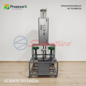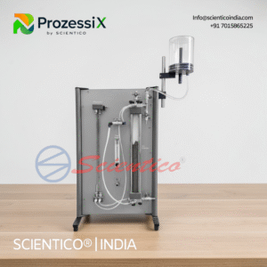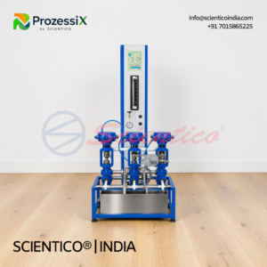

Flapper Nozzle System | Prozessi PX 23
The Flapper Nozzle System Prozessi PX 23 demonstrates the conversion of mechanical motion to pneumatic pressure signals. This Flapper Nozzle System uses a precision flapper-nozzle mechanism with two pressure gauges and a 1 micron dial gauge for measuring displacement-pressure relationships. Two experiments cover flapper-nozzle system operation and gain calculation. Compact design, 300W x 150D x 250H mm, requires clean compressed air at 2 Bar, 50 LPH.
The Flapper Nozzle System Prozessi PX 23 is designed to teach the conversion of mechanical motion into a pressure signal. This Flapper Nozzle System demonstrates how a flapper-nozzle mechanism responds to displacement and generates proportional pressure output, a fundamental principle in pneumatic control devices.
Product Overview
The Flapper Nozzle System Prozessi PX 23 demonstrates the flapper-nozzle conversion mechanism commonly used in industrial process control. The system consists of a flapper-nozzle mechanism where a regulated air supply (typically over 20 psig) flows through a restriction toward an open nozzle. The gap between the nozzle and flapper determines the air escape rate and thus the pressure downstream of the restriction. As the flapper moves, it changes this gap and modulates the output pressure. A precision dial gauge with 1 micron least count measures flapper movement displacement. Two pressure gauges (0-2.5 kg/cm2 range) monitor system pressure and output pressure. An air regulator (0-2 kg/cm2 range) controls the input air supply. The Flapper Nozzle System is compact and simple to operate, measuring 300W x 150D x 250H mm. It requires clean, oil and moisture-free compressed air at 2 Bar pressure, 50 LPH consumption. An optional support table (800W x 800D x 750H mm) is available for laboratory installation.
Flapper Nozzle System Prozessi PX 23 — Technical Specifications
| Specification | Value |
|---|---|
| Product Code | PX 23 |
| Dial Gauge | Least count 1 micron |
| Air Regulator | Range 0-2 kg/cm2 |
| Pressure Gauge 1 | Range 0-2.5 kg/cm2 |
| Pressure Gauge 2 | Range 0-2.5 kg/cm2 |
| Overall Dimensions | W 300 x D 150 x H 250 mm |
| Air Supply Required | Clean, oil and moisture-free air, 2 Bar pressure, 50 LPH consumption |
Technical Data
Flapper-Nozzle Mechanism Components
| Component | Specification |
|---|---|
| Flapper Element | Precision pivoted mechanism |
| Nozzle | Fixed orifice with controlled restriction |
| Gap Adjustment | Variable nozzle-flapper separation |
| Movement Measurement | Micron dial gauge, 1 micron resolution |
Pressure Measurement and Control
| Component | Specification |
|---|---|
| Air Regulator | Range 0-2 kg/cm2, controls input supply pressure |
| Pressure Gauge 1 | Range 0-2.5 kg/cm2, monitors supply pressure |
| Pressure Gauge 2 | Range 0-2.5 kg/cm2, monitors output pressure |
| Pressure Measurement Principle | Differential pressure across restriction varies with flapper gap |
Air Supply Requirements
| Requirement | Specification |
|---|---|
| Air Quality | Clean, oil and moisture-free |
| Supply Pressure | 2 Bar nominal |
| Consumption | 50 LPH |
| Filtration | Oil removal and moisture control required |
Key Features
- Flapper Nozzle System: fundamental pneumatic control device principle demonstration
- Micron dial gauge with 1 micron least count for precision flapper displacement measurement
- Two pressure gauges for simultaneous monitoring of supply and output pressure
- Air regulator for controlled input pressure adjustment
- Compact and simple to operate design
- Direct observation of pressure-displacement relationship
- Industrial standard mechanism used in proportional control valves
Experiments
- Study of Flapper-Nozzle system
- Gain calculation of Flapper-Nozzle system
Construction and Design
The Flapper Nozzle System Prozessi PX 23 is built on a compact assembly measuring 300W x 150D x 250H mm. At the heart of the system is a precision flapper-nozzle mechanism where a pivoted flapper element is positioned above a fixed nozzle opening. Regulated air supply, typically pressurized over 20 psig, flows through a restriction toward the open nozzle. Air escapes through the variable gap between the flapper and nozzle tip, creating a back-pressure that varies inversely with the gap size. As the flapper moves mechanically, the gap changes, modulating the output pressure. A precision dial gauge with 1 micron least count measures flapper displacement directly. Two pressure gauges (0-2.5 kg/cm2 range each) display supply pressure and output pressure simultaneously, allowing students to observe the pressure-motion relationship. An air regulator (0-2 kg/cm2 range) controls input air supply, enabling gain variation studies. The system requires clean, oil and moisture-free compressed air at 2 Bar pressure, consuming 50 LPH. An optional support table (800W x 800D x 750H mm) is available for secure laboratory mounting.
Operating Principle
The Flapper Nozzle System converts mechanical flapper displacement into proportional pneumatic pressure output. As flapper-nozzle gap increases, air escapes more freely, reducing back-pressure. As the gap decreases, air escape is restricted, increasing back-pressure. This linear or near-linear relationship between displacement and pressure is the fundamental operating principle of pneumatic proportional control devices and pilot-operated regulators.
Scope of Delivery
- Flapper Nozzle System Prozessi PX 23 complete assembly
- Precision flapper-nozzle mechanism with adjustable gap
- Dial gauge, least count 1 micron
- Air regulator, range 0-2 kg/cm2
- Pressure gauge, range 0-2.5 kg/cm2 (first unit)
- Pressure gauge, range 0-2.5 kg/cm2 (second unit)
- Air inlet and outlet connections
- Base assembly, 300W x 150D x 250H mm
- User documentation and experimental manual
- Air supply hose connections
Optional Accessories
- Support table, size 800W x 800D x 750H mm
- Mini compressor for independent air supply
- Replacement dial gauge unit
Q1: What is the purpose of the Flapper Nozzle System?
A: The Flapper Nozzle System demonstrates how mechanical motion (flapper displacement) is converted into proportional pneumatic pressure signals, a fundamental principle in industrial control devices.
Q2: How does the flapper-nozzle mechanism work?
A: As the flapper moves closer to the nozzle, the gap decreases, restricting air escape and increasing back-pressure. As the flapper moves away, air escapes more freely, decreasing pressure. This creates a proportional relationship between displacement and pressure.
Q3: What is the resolution of the dial gauge?
A: The dial gauge has a least count of 1 micron, allowing precise measurement of very small flapper displacements.
Q4: What does the Flapper Nozzle System gain calculation measure?
A: The gain calculation measures how much the output pressure changes for a given change in flapper displacement, typically expressed as pressure change per unit displacement (kg/cm2 per micron).
Q5: What air supply is required for the Flapper Nozzle System?
A: The system requires clean, oil and moisture-free compressed air at 2 Bar pressure with a consumption of 50 LPH. Air must be filtered to remove oil and moisture.
Need Assistance? We're Here to Help!
Connect with our team for product specifications, pricing, and customized solutions for your institution or project.