
Vibration Experiment: Free, Forced and Damped Vibration Procedure Using Vibration Test Rig
The vibration experiment is a key laboratory exercise in the Dynamics and Theory of Machines syllabus for mechanical engineering programmes. It uses a vibration test rig to demonstrate the principles of free undamped vibration, free damped vibration, and forced vibration with resonance. This guide covers the complete theory of single-degree-of-freedom (SDOF) systems, experimental procedure using a standard motorised vibration test rig, observation tables, and calculation of natural frequency, damping ratio, and resonance frequency.
Equipment mentioned in this guide
Review the product information, specifications and model before requesting a quotation.
Vibration Test Rig Manufacturer India – Spring Mass System
The Vibration Test Rig (Spring-Mass System) is used to study free and forced vibrations of single and multi-degree of freedom systems. Students determine natural frequency, damping ratio, amplitude-frequency response, and resonance, fundamental concepts in mechanical and structural engineering laboratory courses.
View product details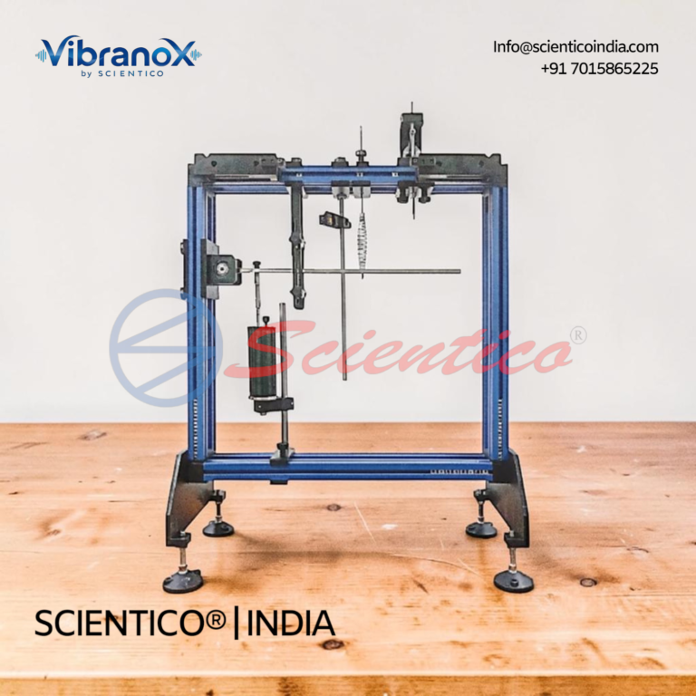
Free & Forced Vibration Apparatus | Vibrano X – 08
The Free & Forced Vibration Apparatus - Vibrano X - 08 trainer covers free, damped, and forced vibrations in mechanical vibration technology. It is mounted on a sturdy, low-vibration frame with quick fastening elements for accurate experimental set-up. This Free & Forced Vibration Apparatus consists of spring mass and rigid beam vibration study sections.
View product detailsObjectives
- To determine the natural frequency of a spring-mass system by free vibration experiment and compare with the theoretical value.
- To determine the damping coefficient and damping ratio from a free damped vibration experiment using the logarithmic decrement method.
- To plot the frequency response curve (amplitude vs frequency) for forced vibration and identify the resonance frequency.
Theory
Free Undamped Vibration
Natural frequency: omega_n = root(k/m) rad/s, or f_n = (1/2pi) x root(k/m) Hz
Time period: T = 1/f_n = 2pi x root(m/k) seconds
Free Damped Vibration
Logarithmic decrement: delta = (1/n) x ln(x1/x(n+1)), where x1 and x(n+1) are amplitudes of successive cycles n apart.
Damping ratio: zeta = delta / root(4pi squared + delta squared)
Forced Vibration
At resonance, the forcing frequency equals the natural frequency: omega = omega_n. At resonance, amplitude is maximum and is limited only by damping.
Magnification factor: MF = X / (F/k) = 1 / root((1 – r squared)squared + (2 zeta r)squared), where r = omega / omega_n
Apparatus
Scientico model-specific vibration test rig includes:
- Beam-and-spring assembly with adjustable mass positions
- Interchangeable spring sets (multiple stiffness values)
- Variable-speed eccentric motor (0-1500 rpm) for forced vibration excitation
- Digital tachometer for excitation frequency measurement
- Amplitude measurement scale with pointer or LVDT sensor
- Viscous damper with adjustable dashpot for damping ratio variation
- Data acquisition interface (optional computerised version)
Part A: Free Undamped Vibration Procedure
- Set up the beam with the test mass at the specified position. Note the spring stiffness k (N/m) from the apparatus data sheet.
- Calculate theoretical natural frequency: f_n(theory) = (1/2pi) x root(k/m).
- Give the mass a small initial displacement (10-15 mm) and release. Start the stopwatch simultaneously.
- Count 10 complete oscillations and record the total time t. Calculate T = t/10 (period) and f_n = 1/T.
- Repeat three times and average the period.
- Vary the mass (add extra weights) and repeat to show the effect of mass on natural frequency.
Part B: Free Damped Vibration Procedure
- Engage the dashpot damper at the lowest damping setting.
- Give the mass a measured initial displacement x0 (20-25 mm). Release and allow to oscillate freely.
- Record the amplitude of successive peaks: x1, x2, x3, x4, x5 using the scale pointer.
- Calculate logarithmic decrement: delta = (1/4) x ln(x1/x5).
- Calculate damping ratio: zeta = delta / root(4pi squared + delta squared).
- Increase dashpot setting and repeat to show effect of increased damping.
Part C: Forced Vibration and Resonance
- Switch on the eccentric motor. Set the minimum speed.
- At each motor speed setting, allow the system to reach steady-state (30-60 seconds). Record motor speed N (rpm) and steady-state amplitude X (mm).
- Increase motor speed in steps of 50-100 rpm. Take 15-20 readings from well below to well above the expected resonance frequency.
- Plot X vs N (or X vs frequency f). Identify the resonance peak (maximum amplitude).
- Compare the resonance frequency with the natural frequency from Part A.
Observation Tables
Part A, Free Undamped Vibration: Spring stiffness k = _____ N/m | Mass m = _____ kg
| Trial | Time for 10 oscillations (s) | Period T (s) | Experimental f_n (Hz) | Theoretical f_n (Hz) | % Error |
|---|---|---|---|---|---|
| 1 | |||||
| 2 | |||||
| 3 |
Part B, Free Damped Vibration:
| Amplitude x1 (mm) | x2 (mm) | x3 (mm) | x4 (mm) | x5 (mm) | Log decrement delta | Damping ratio zeta |
|---|---|---|---|---|---|---|
Precautions
- Keep initial displacement small (below 15% of static deflection) to maintain linear SDOF behaviour.
- For forced vibration, approach resonance slowly, amplitude increases rapidly near resonance and can damage the apparatus if not controlled.
- Ensure all bolts on the beam and spring are tight before each test.
- For the damped test, ensure dashpot oil level is correct, low oil gives under-estimated damping ratio.
Related Experiments
Perform alongside the governor apparatus experiment. Browse Scientico vibration technology equipment and full Theory of Machines lab range. Request a CIF proforma invoice within 48 hours for export orders.
{“@context”:”https://schema.org”,”@type”:”HowTo”,”name”:”Vibration Experiment Procedure, Free, Forced, and Damped Vibration”,”description”:”Step-by-step procedure for free, forced, and damped vibration experiments using a spring-mass system and vibration test rig.”,”totalTime”:”PT3H”,”step”:[{“@type”:”HowToStep”,”position”:1,”name”:”Setup, Free Vibration”,”text”:”Set up the spring-mass system. Measure the static deflection (δ) of the mass. Calculate theoretical natural frequency: ωn = √(g/δ) or ωn = √(k/m).”},{“@type”:”HowToStep”,”position”:2,”name”:”Conduct Free Vibration Test”,”text”:”Displace the mass by a small amount (within linear range) and release. Record time for 10 complete oscillations using a stopwatch. Calculate experimental natural frequency.”},{“@type”:”HowToStep”,”position”:3,”name”:”Damped Vibration Setup”,”text”:”Add the damping unit (dashpot). Start with minimum damping. Displace and release the mass. Observe decay of oscillations.”},{“@type”:”HowToStep”,”position”:4,”name”:”Measure Damping”,”text”:”Record successive amplitudes A₁, A₂, A₃… Calculate logarithmic decrement: δ = ln(A₁/A₂). Damping ratio ζ = δ/√(4π²+δ²).”},{“@type”:”HowToStep”,”position”:5,”name”:”Forced Vibration Setup”,”text”:”Connect the eccentric motor (exciter) to the spring-mass system. Start the exciter at low frequency. Record amplitude of vibration at each exciter frequency.”},{“@type”:”HowToStep”,”position”:6,”name”:”Find Resonance Frequency”,”text”:”Increase exciter speed in steps. Plot amplitude vs frequency. The peak amplitude occurs at resonant frequency (ωr ≈ ωn for lightly damped systems).”},{“@type”:”HowToStep”,”position”:7,”name”:”Plot Frequency Response”,”text”:”Plot amplitude ratio (X/Xst) vs frequency ratio (ω/ωn). Compare with theoretical magnification factor M = 1/√((1-(ω/ωn)²)²+(2ζω/ωn)²).”}]}Get Specifications & Pricing
Scientico India manufactures laboratory apparatus under an ISO 9001:2015 quality system. Conformity documentation is confirmed for each quoted model. Contact us for full specifications, pricing, and documentation.
WhatsApp: +91 701-586-5225 | [email protected] | FAQ, Shipping, Payment & Warranty
Scientico India manufactures this and the full range of Theory of Machines equipment, model-specific and supplied to engineering colleges worldwide.
Explore Theory of Machines Equipment → or request a quoteOne honest ask
We don't gate anything on this site. You just read the whole thing free. If it was useful, leave your email and two things happen: we send you this page as a plain-text block you can paste into a tender file or an internal email, and we notify you the next time we publish a buyer tool like this one. Nothing else. No drip sequence, no sales calls booked without asking.