
The worm and worm wheel experiment can be used to determine the velocity ratio, mechanical advantage and efficiency of a worm-gear lifting apparatus. Students measure the effort and load geometry, apply a sequence of loads, record the corresponding effort, and compare the measured result with the ideal kinematic ratio. The actual apparatus dimensions and number of worm starts must be read from the equipment being used; do not assume values from another setup.
Equipment mentioned in this guide
Review the product information, specifications and model before requesting a quotation.
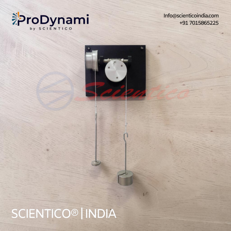
Worm And Wheel Apparatus | ProDynami – 1224
The Worm And Wheel Apparatus ProDynami - 1224 studies the performance of a worm and wheel mechanism, containing a circular gear and a toothed rod. This Worm And Wheel Apparatus converts or transmits circular motion to linear motion or vice versa. It uses pulleys, cord, and hangers to apply load and effort forces.
View product detailsAim
To calculate the velocity ratio, mechanical advantage and efficiency of the worm-and-wheel apparatus from measured dimensions and readings, and to examine the relationship between load and effort within the apparatus's safe operating range.
Apparatus and measurements
- Worm and worm-wheel lifting apparatus with effort wheel or handle and load drum.
- Load and effort hangers with a suitable set of masses, used within the apparatus rating.
- Measuring rule or caliper suitable for measuring the effective effort-wheel and load-drum radii.
- Means to count the worm-wheel teeth and the number of starts on the worm, using the apparatus drawing or a direct inspection.
- Observation sheet for load, effort, units, dimensions, direction of motion and repeat readings.
Use effective radii at the line of action of the cord or force, not an outside diameter unless that is the intended working radius. Identify whether the load and effort are recorded as masses or forces. If masses are used, convert consistently when calculating force-based mechanical advantage; use the same gravitational conversion for both so the ratio remains meaningful.
Theory and formulas
Let R be the effective effort-wheel radius, r the effective load-drum radius, T the number of teeth on the worm wheel, and n the number of starts on the worm. During one revolution of the worm, the wheel advances by n teeth. The corresponding ideal velocity ratio is:
Velocity ratio, VR = (R × T) / (r × n)
This geometry-based expression assumes the described lifting-machine arrangement and the measured effective radii. If your apparatus uses a different transmission or the manufacturer supplies a specific calculation method, follow the apparatus manual and state the method in the report.
For each reading, calculate:
- Mechanical advantage, MA = W / P, where W is the applied load force and P is the effort force for the same reading.
- Efficiency, η = (MA / VR) × 100%, using the same unit convention and the VR calculated from the measured geometry.
If the experiment includes the law of the machine, fit the observed effort-load readings to P = mW + C over the tested range, with a clearly stated unit for P and W. Do not extrapolate the line beyond the tested loads or treat a regression as a guaranteed performance specification.
Procedure
- Check the apparatus, support, cords, hangers and load path. Read the operating instructions and confirm the safe working limit before adding any mass.
- Record the equipment identifier and inspect the effort wheel, worm, wheel and load drum for visible damage or loose parts.
- Measure the effective effort radius R and load-drum radius r at the point where the cord acts. Record units and repeat each measurement if the geometry is uncertain.
- Record the worm-wheel tooth count T and worm-start count n. If the number of starts cannot be confirmed visually, use the equipment drawing or manual.
- Calculate the theoretical VR from the stated arrangement before collecting load-effort readings. Show the substitutions and unit basis in the report.
- Set the unloaded apparatus to the starting position. Add a known load within the rated range, then apply effort smoothly until the load rises at a steady rate. Record the effort reading and direction.
- Repeat across several approved load levels. Keep the same winding direction and method; avoid shock loading, sudden release or placing hands under a suspended load.
- Where required, repeat each reading and calculate a mean. Record friction, cord slip, eccentric winding or inconsistent motion as observations rather than silently discarding the reading.
- Calculate MA and efficiency for each pair of readings. Plot load against effort using labelled axes and units if required by the laboratory manual.
- After unloading, reset the apparatus and report the measured geometry, readings, equations, graph, uncertainty and limitations.
Observation table
Use the table format prescribed by the instructor or manual. This blank structure helps keep the units and measurements together; it does not supply expected results.
| Reading | Load W (unit) | Effort P (unit) | Repeat / mean | MA = W/P | VR | Efficiency η (%) | Observation |
|---|---|---|---|---|---|---|---|
| 1 | Calculated from R, r, T, n | ||||||
| 2 | Same measured geometry | ||||||
| 3 | Same measured geometry |
How to interpret the result
Compare measured effort and load readings with the calculated velocity ratio and describe the trend over the tested range. Differences between ideal and measured behaviour may arise from friction, cord winding, alignment, measurement uncertainty, changing effective radius or reading technique. State what was observed on your apparatus rather than inserting a textbook efficiency value as though it were measured.
Self-locking is not guaranteed by the name “worm gear” or by one efficiency reading. Whether a particular worm drive can resist back-driving depends on its geometry and friction conditions, including lead angle, materials, lubrication and operating state. Do not release a suspended load to test this. Any back-driving demonstration must follow a specific approved laboratory procedure, use a secured test setup and stay within the apparatus instructions.
Common errors to check
- Using an outside diameter instead of the effective cord radius.
- Confusing worm starts with worm-wheel teeth.
- Mixing mass values in one column with force values in another.
- Recording effort before the load moves steadily or changing the winding direction between observations.
- Ignoring cord layers or slip that change the effective drum radius.
- Calculating efficiency from an unverified VR or reporting more precision than the measurements support.
- Claiming that every worm drive is self-locking or assigning a universal efficiency threshold without design data.
Buying a Worm and Wheel Apparatus for this experiment
An equipment RFQ should describe the practical students must complete as well as the product name. A mechanism-display model, a manually loaded experiment and a powered gear test stand serve different teaching tasks. For the load-and-effort experiment on this page, ask each supplier to identify the actual force application, working geometry, readings and calculation method in the offered arrangement.
The current Worm And Wheel Apparatus | ProDynami – 1224 listing is the catalogue reference to discuss with Scientico. Request the current drawing, included components and operating instructions before finalising the BOQ. Do not transfer a tooth count, working radius, load limit or transmission ratio from another manufacturer's apparatus into this model's specification.
Compare the complete experiment package
| Buyer check | Supplier response to request |
|---|---|
| Geometry for the calculation | Identify the worm starts, wheel teeth and relevant effective working radii, or provide the model-specific method used to obtain the velocity ratio. |
| Load and effort readings | List the hangers, masses, cords, measuring items and recording method included in the offer. State the units and the apparatus operating limits. |
| Installation boundary | State the required support or mounting arrangement, available working space and any buyer-supplied fixings or services. |
| Documents and demonstration | Identify the manual, parts list and observation sheet. Agree a demonstration within the stated limits using the supplied method. |
Write an observable acceptance task
A useful handover task is to identify the supplied components, confirm the working geometry, obtain repeat load-and-effort observations and calculate mechanical advantage and efficiency using consistent units. The institution should agree the permitted operating conditions and acceptance criteria with the supplier before ordering. An example result from another laboratory is not a guaranteed reading for the delivered apparatus.
Keep any discussion of back-driving separate from the purchase assumption that a load will hold itself. Request the manufacturer's stated precautions and follow the approved laboratory procedure. An assumed self-locking action must not be used as protection for a suspended load.
Information that helps a manufacturer answer the enquiry
Send the required practical, course or laboratory, number of stations, destination, proposed catalogue reference and any mandatory tender clauses. Attach the calculation or observation format if it is prescribed by the department. Ask the quotation to distinguish included teaching items, optional accessories, recurring consumables and installation responsibilities.
Use the equipment RFQ checklist for the purchasing information and the Theory of Machines equipment category to review related apparatus. Request a Worm and Wheel Apparatus quotation with the experiment and destination so the offered scope can be reviewed line by line.
For related mechanisms, compare screw jack efficiency experiment and winch crab experiment. Use the geometry and operating instructions of each apparatus.
Frequently asked questions
How do you calculate the velocity ratio of a worm and worm wheel?
For the lifting-machine arrangement described here, VR = (R × T)/(r × n), where R and r are effective radii, T is wheel teeth and n is worm starts. Confirm the apparatus geometry and manual before using the expression.
How do you calculate efficiency?
Calculate MA = W/P using consistent load and effort units, then η = (MA/VR) × 100%. Use the velocity ratio from the measured dimensions and report the reading and unit basis.
Is every worm and worm wheel self-locking?
No. Back-driving behaviour depends on the specific design and friction conditions. Follow the manual and an approved safe test method; never rely on an assumed self-locking action to hold a suspended load.
Why can the measured efficiency differ between readings?
Friction, winding radius, alignment, cord slip, loading direction and measurement technique can affect readings. Record repeat observations and discuss the conditions of the test.