
A composite-wall heat-transfer experiment shows how heat passes through adjoining solid layers when a temperature difference is maintained across them. Students record temperatures at the available measurement points, build a temperature profile, and compare the observed behavior with a one-dimensional thermal-resistance model. This guide explains the calculation, a careful lab workflow, common sources of error, and the equipment details a buyer should confirm before requesting a quotation.
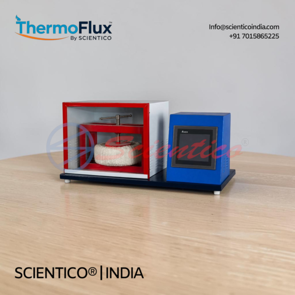
For the named product route, see the Heat Transfer through Composite Wall Apparatus (ThermoFlux-2904). Its published record describes M.S., Bakelite and press-wood plates, thermocouples at slab interfaces, a variable heater control, digital voltage and current indication, and a multi-channel temperature display. Confirm the final supplied configuration and documentation in the written offer.
Equipment mentioned in this guide
Review the product information, specifications and model before requesting a quotation.
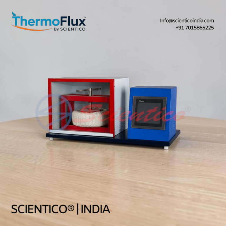
Heat Transfer through Composite Wall Apparatus | ThermoFlux-2904
The Heat Transfer through Composite Wall Apparatus ThermoFlux-2904 is engineered to determine total thermal conductivity of a composite wall and plot temperature gradients along the composite wall structure. This apparatus enables accurate measurement of heat transfer characteristics across layered materials through controlled experimental conditions.
View product detailsWhat the experiment is intended to show
The experiment connects Fourier’s law to a layered wall. Under the simplifying assumptions of steady, one-dimensional conduction, constant cross-sectional area, known layer thicknesses and properties, and negligible lateral heat loss, each layer contributes a conduction resistance. For layers in series, those resistances add. A measured temperature drop across a layer is therefore related to the heat rate and that layer’s resistance.
University lab manuals commonly frame the exercise around plotting temperature across the wall and determining an overall thermal response; the exact apparatus arrangement, sensor count, water circuit, plate materials and procedure vary. Follow the manual supplied for the selected apparatus rather than transferring settings or measurements from another institution’s rig.
Core equations for a plane composite wall
For layer i, the ideal one-dimensional conduction resistance is:
Ri = Li / (kiA)
where L is the layer thickness, k is its thermal conductivity and A is the area normal to heat flow. For layers in series, with the same area and no significant bypass path:
Rtotal = ΣRi and Q = (Thot − Tcold) / Rtotal
The heat flux is q″ = Q/A. If an equivalent conductivity is required for the complete layered thickness, the ideal series model gives keff = Ltotal / Σ(Li/ki). These relations require consistent SI units and stated assumptions. Do not calculate a numeric conductivity from the product listing alone: its public record does not specify every layer thickness or a full calibration protocol.
Procedure: collect a defensible temperature profile
- Identify the stack and measurement points. Record the actual layer order, dimensions, sensor labels and contact arrangement from the supplied manual. Do not infer the order or thickness from another apparatus.
- Check the setup before energizing. Confirm the required supply, earthing, controls and connections against the manufacturer’s instructions. Begin with the heater control at the prescribed safe starting position.
- Choose an approved input condition. Set only an input permitted by the equipment manual and the institution’s laboratory procedure. Record the displayed voltage and current; electrical input VI is not automatically identical to heat conducted through the test section because losses may occur.
- Wait for the specified steady condition. Follow the manual’s stabilization criterion. Record all available temperatures together with the input readings and any other measurements the selected configuration actually provides.
- Repeat at further approved settings. Change one controlled input at a time, allow the system to stabilize again, and record a complete set. Do not exceed published operating limits.
- Plot temperature against position. Use the real sensor locations and layer boundaries. A slope change can be discussed in relation to layer properties and contact interfaces, but it should not be assigned a material value without the needed geometry and calibration data.
- Compare theory and experiment. Calculate the ideal series resistance only where thicknesses, conductivities and area are known. Discuss deviations as possible effects of contact resistance, heat loss, sensor placement, non-steady readings or uncertainty—not as proof of a fault by themselves.
Observation sheet: record the variables, not just the final answer
| Record | Why it matters |
|---|---|
| Run identifier and date | Connects readings to the correct apparatus setup and lab record. |
| Layer material, order, thickness and effective area | Defines the geometry and inputs for the series-resistance model. |
| Sensor label and position for each temperature | Makes the temperature profile interpretable and repeatable. |
| Voltage, current and heater-control setting | Documents the electrical operating condition; VI is an input reference, not automatically the wall heat rate. |
| Time or stabilization note | Shows whether the reading followed the prescribed steady-state procedure. |
| Ambient conditions and operator notes | Helps explain repeatability differences and unexpected heat loss. |
| Calculated resistance, heat rate or effective conductivity | Preserves the assumptions, units and source values used in the calculation. |
Common errors and how to prevent them
- Using a value from a different apparatus: material sequence, dimensions, sensors and cooling arrangements vary. Use the supplied model’s record and manual.
- Treating electrical power as measured wall heat flow: heater input can include losses. State the method used to estimate heat flow and its limits.
- Taking readings before stabilization: transient values can distort a steady-state comparison. Apply the manual’s stabilization rule consistently.
- Ignoring interfaces: imperfect contact can add resistance and change the temperature drop. Note the clamping/contact procedure and do not over-tighten beyond the manual.
- Mixing units: convert thickness to metres, area to square metres, conductivity to W/(m·K), and temperatures to a consistent scale for differences.
- Reporting false precision: include instrument resolution and repeated-reading variation; avoid more significant figures than the measurements support.
Choosing an apparatus for a teaching laboratory
When evaluating a composite-wall apparatus, compare what the learner can measure and what the institution must provide—not just the product name. Ask the supplier to confirm in writing:
- the exact layer materials, count, order, thickness and effective heat-transfer area;
- heater arrangement, control range and any stated operating limits;
- temperature-sensor type, number, locations, indicator channels and calibration records, where applicable;
- whether heat flow is inferred from electrical input or measured through an additional method or accessory;
- electrical supply, earthing, footprint, utilities, supplied accessories and installation boundary;
- which experiments, student measurements and calculations are supported by the supplied configuration;
- the manual, conformity documents, warranty terms and any tender-specific forms requested by the buyer.
Use the laboratory-equipment RFQ checklist to structure the request, and browse the thermodynamics lab equipment catalogue if the requirement includes more than one heat-transfer experiment. The broader heat-transfer lab planning guide helps place a single apparatus within a course or lab plan.
Questions to settle before the quotation
Can the experiment produce a temperature profile?
The live ThermoFlux-2904 record describes thermocouples at slab interfaces and a multi-channel temperature indicator. Confirm the supplied sensor count and measurement positions for the offered configuration.
Can I calculate the wall’s effective thermal conductivity?
The ideal calculation needs the layer thicknesses, area, temperatures and appropriate material-property inputs. Request any dimensions and calibration information needed for your lab’s calculation; the product page does not publish every required value.
Does the experiment measure heat flow directly?
The product record lists voltage, current and temperatures. It does not establish a separate direct heat-flow measurement method. Ask the supplier to identify the measurement method and explain how heat losses are treated in the supplied manual.
Are the published details a tender datasheet?
The product page is a catalogue record. For a tender, request a model-specific quotation and confirm final dimensions, scope, documents, accessories and compliance responses against the tender’s own requirements.
Request a model-matched technical quotation
When enquiring about the Heat Transfer through Composite Wall Apparatus, include the ThermoFlux-2904 reference, quantity, destination, course or experiment objective, required measurements, utility conditions and tender/document requirements. Ask for any missing layer dimensions and sensor details needed to validate your calculation plan. For broader selection, return to the heat-transfer experiments and equipment guide.
References and scope
This guide explains the standard idealized series-resistance model and common lab-recording steps. Institutional manuals demonstrate that specific procedures and apparatus arrangements vary: see the K.L.N. College of Engineering heat-transfer lab manual and the An-Najah National University heat-transfer manual. Their particular material values, heater settings and sensor configurations are not presented here as ThermoFlux-2904 specifications. For procurement decisions, rely on the selected model’s written technical offer and supplied instructions.
One honest ask
We don't gate anything on this site. You just read the whole thing free. If it was useful, leave your email and two things happen: we send you this page as a plain-text block you can paste into a tender file or an internal email, and we notify you the next time we publish a buyer tool like this one. Nothing else. No drip sequence, no sales calls booked without asking.