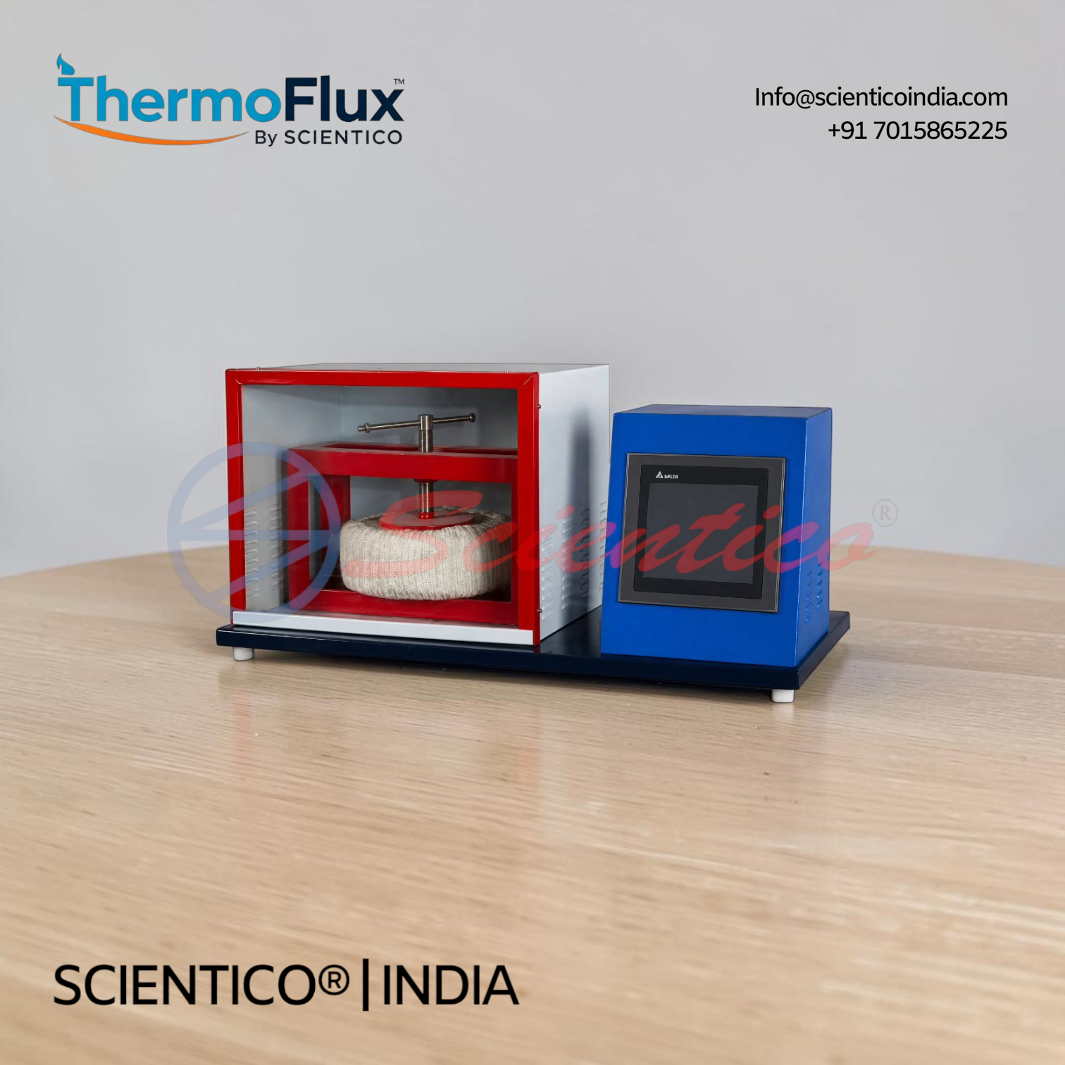
Heat Transfer through Composite Wall Apparatus | ThermoFlux-2904
The Heat Transfer through Composite Wall Apparatus ThermoFlux-2904 determines total thermal conductivity and plots temperature gradients across composite wall structures. Features M.S., Bakelite, and Press wood plates with embedded thermocouples at slab interfaces. Digital instrumentation includes 0-199.9 V voltmeter, 0-1.999 A ammeter, multi-channel temperature indicator, and dimmer stat control for variable thermal loads. Requires 230 V.A.C. stabilized supply and 1.5 m × 1.5 m floor space.
Experiment procedure: use the composite wall heat-transfer experiment guide for the calculation method and measurement checklist.
The Heat Transfer through Composite Wall Apparatus ThermoFlux-2904 is engineered to determine total thermal conductivity of a composite wall and plot temperature gradients along the composite wall structure. This apparatus enables accurate measurement of heat transfer characteristics across layered materials through controlled experimental conditions.
Product Overview
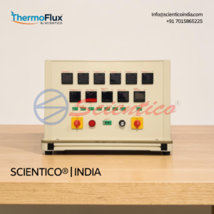
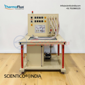
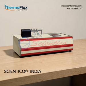
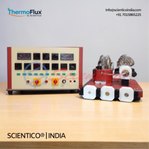
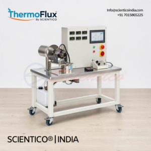
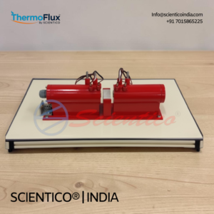
The Heat Transfer through Composite Wall Apparatus ThermoFlux-2904 consists of a central nichrome wire heater wound on mica and sandwiched between two aluminum plates. Three identical slabs of M.S., Bakelite, and Press wood, each 200 mm diameter, are stacked on both sides of the heater to form a composite wall structure. A hand press ensures perfect contact between slabs. Thermocouples embedded at slab interfaces measure temperatures at respective surfaces. Digital voltage (0-199.9 volts) and ammeter (0-1.999 amp) readings allow precise heater input control via dimmer stat. A multi-channel digital temperature indicator logs all thermocouple data. The assembly is housed in an enclosure with a Perspex window for observation. Experiments can be conducted at various input levels for comparative thermal analysis.
Heat Transfer through Composite Wall Apparatus ThermoFlux-2904 — Technical Specifications
| Specification | Details |
|---|---|
| Composite Wall Assembly | M.S., Bakelite, and Press wood plates, 200 mm diameter |
| Heater Type | Nichrome wire heater on mica, sandwiched between aluminum plates |
| Enclosure | Perspex window for visibility |
| Temperature Measurement | Thermocouples at slab interfaces |
| Voltage Range | 0-199.9 volts (digital display) |
| Ammeter Range | 0-1.999 amp (digital display) |
| Temperature Indicator | Multi-channel digital indicator |
| Heater Control | Dimmer stat for variable input |
| Power Supply | 230 V.A.C. stabilized with earthing |
| Floor Space | 1.5 m × 1.5 m at working height |
Technical Data
Heater Assembly
- Heater element: Nichrome wire on mica
- Mounting: Sandwiched between two aluminum plates
- Thermal interface: Ensures uniform heat distribution
Composite Wall Structure
- Material 1: M.S. plate, 200 mm dia
- Material 2: Bakelite plate, 200 mm dia
- Material 3: Press wood plate, 200 mm dia
- Configuration: Three identical slabs on each side of heater
- Contact mechanism: Hand press for uniform pressure
Instrumentation
- Voltage measurement: Digital, 0-199.9 volts
- Current measurement: Digital, 0-1.999 amp
- Temperature channels: Multi-channel digital display
- Control: Dimmer stat for adjustable heating
Key Features
- Composite wall assembly: M.S., Bakelite, and Press wood plates at 200 mm diameter for standardized testing
- Nichrome wire heater: Wound on mica, sandwiched between aluminum plates for uniform heat transfer through composite wall materials
- Hand press mechanism: Ensures perfect contact between slabs for accurate thermal conductivity measurement
- Thermocouple placement: Embedded at slab interfaces to measure temperature gradients across the composite wall
- Digital instrumentation: Voltage (0-199.9 V) and ammeter (0-1.999 A) for precise heater input control
- Multi-channel temperature indicator: Simultaneous reading of all thermocouple data
- Dimmer stat control: Variable input for experiments at different thermal loads
- Perspex observation window: Clear visibility of composite wall assembly during operation
- Stabilized power supply: 230 V.A.C. with earthing for safe, consistent operation
Experiments
- Determine total thermal conductivity of composite wall structure
- Plot temperature gradient along the composite wall at steady state
- Compare thermal conductivity across different material combinations
- Analyze heat transfer rate at various heater input levels
- Measure temperature distribution at slab interfaces
- Investigate thermal resistance of individual layers in the composite wall
- Study effect of contact pressure on thermal conductivity measurement
Construction and Design
The Heat Transfer through Composite Wall Apparatus ThermoFlux-2904 features a composite wall assembly consisting of three identical slabs of M.S., Bakelite, and Press wood, each 200 mm in diameter. A nichrome wire heater wound on mica is sandwiched between two aluminum plates and positioned centrally. A hand press provides controlled contact pressure between all slabs. Thermocouples are embedded at each interface between slabs to measure localized temperatures. The entire assembly is housed in an enclosure with a Perspex window for safe observation. Digital voltage and ammeter displays provide real-time heater input data. A multi-channel digital temperature indicator logs all thermocouple readings simultaneously. The dimmer stat allows operators to adjust heater input for variable thermal load testing.
Scope of Delivery
- Composite wall assembly with M.S., Bakelite, and Press wood plates
- Nichrome wire heater on mica between aluminum plates
- Hand press mechanism
- Thermocouples (complete set for interface measurement)
- Enclosure with Perspex window
- Digital voltage meter (0-199.9 V)
- Digital ammeter (0-1.999 A)
- Multi-channel digital temperature indicator
- Dimmer stat control unit
- Power cord with earthing
Required for Operation
- 230 V.A.C. stabilized power supply with earthing
- Floor space: 1.5 m × 1.5 m at working height
- Level surface for apparatus placement
Optional Accessories
- Software for data acquisition on LabView
- HMI touchscreen panel for easy usage and data logging
Q: What is the maximum heater input voltage for the ThermoFlux-2904?
A: The digital voltage meter ranges from 0-199.9 volts, and the dimmer stat allows you to set the heater input within this range for controlled thermal experiments.
Q: How are temperatures measured in the composite wall structure?
A: Thermocouples are embedded at the interfaces between each slab. A multi-channel digital temperature indicator displays readings from all thermocouples simultaneously, showing the temperature gradient across the composite wall.
Q: What materials are included in the composite wall assembly?
A: The composite wall assembly consists of three types of identical slabs: M.S. (mild steel), Bakelite, and Press wood, each 200 mm in diameter. These are stacked on both sides of the central heater.
Q: Why is the hand press important?
A: The hand press ensures perfect contact between all slabs, which is critical for accurate thermal conductivity measurement and consistent heat transfer across the composite wall interfaces.
Q: Can experiments be conducted at different heater input levels?
A: Yes, the dimmer stat allows variable adjustment of heater input, enabling experiments at various thermal loads and generation of comparative thermal data for the composite wall structure.
Need Assistance? We're Here to Help!
Connect with our team for product specifications, pricing, and customized solutions for your institution or project.