
The gyroscope experiment is a fundamental practical in the Theory of Machines laboratory that demonstrates the principle of gyroscopic couple, the torque that acts on a spinning rotor when its axis of rotation is forced to change direction. This principle governs the stability of ships, aircraft, and satellites, and is exploited in navigation gyroscopes, gyrocompasses, and stabiliser systems.
Equipment mentioned in this guide
Review the product information, specifications and model before requesting a quotation.
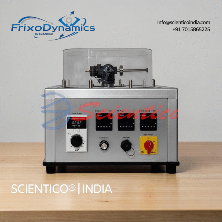
Gyroscope Apparatus | FrixoDynamics FX-505
The SCIENTICO FrixoDynamics FX-505 Gyroscope Apparatus is a self-contained, motorised laboratory unit designed for the experimental study of gyroscopic principles, precession, and the moments generated by rotating bodies. It provides students with direct, observable evidence of gyroscopic behaviour under controlled and adjustable conditions. Both the flywheel speed and the frame rotation speed are independently regulated and digitally displayed, allowing systematic investigation across a range of operating parameters. The FX-505 is a portable, table-mounted unit requiring only a standard power supply, and is manufactured by SCIENTICO for supply to engineering institutions and distributors worldwide.
View product details
Static and Dynamic Balancing | Vibrano X – 02
The Static and Dynamic Balancing - Vibrano X - 02 unit is designed to study the balancing of rotating objects. It demonstrates how centrifugal force unbalances a rotating assembly at any given velocity. This Static and Dynamic Balancing apparatus provides a bench top platform for analyzing both static and dynamic unbalance conditions.
View product details
Static and Dynamic Balancing | ProDynami 1268
The Static and Dynamic Balancing ProDynami 1268 unit is designed to study the balancing of rotating objects. This Static and Dynamic Balancing apparatus demonstrates how centrifugal force unbalances an assembly when an object rotates at a given velocity.
View product detailsAim of the Experiment
1. To study the principle of gyroscopic action and precession.
2. To verify the relationship between the gyroscopic couple (C), moment of inertia (I), angular velocity of spin (ω), and angular velocity of precession (Ω): C = I × ω × Ω
Theory
Angular Momentum and Gyroscopic Effect
A spinning rotor possesses angular momentum H = Iω, where I is the moment of inertia about the spin axis. When a couple (torque) C is applied perpendicular to the spin axis, the rotor does not tilt in the direction of the applied couple. Instead, the spin axis rotates, this is called precession.
The gyroscopic couple equation: C = I × ω × Ω
where C = gyroscopic couple (N·m), I = mass moment of inertia of rotor (kg·m²), ω = spin velocity (rad/s), Ω = precession velocity (rad/s)
Right-Hand Rule for Precession Direction
The precession velocity vector Ω is perpendicular to both the angular momentum vector H and the applied couple vector C, governed by: C = Ω × H (vector cross product)
Gyroscopic Couple in Engineering Applications
- Ships: Rolling of a ship induces gyroscopic couple on the propeller shaft, this couple tends to yaw the ship. Naval architects must account for this in propeller and rudder design.
- Aircraft: Gyroscopic couple from propeller rotation affects aircraft pitching and yawing, pilots must apply corrective rudder when pulling out of a dive.
- Motorcycles: Gyroscopic effect of rotating wheels provides stability, at speed, the wheel resists change in its plane of rotation, keeping the motorcycle upright.
- Gyrocompasses: Earth’s rotation causes precession of a free gyroscope, aligning it with true north, the basis of gyrocompass navigation.
Apparatus Required
- Gyroscope apparatus (motorised spinning disc with horizontal and vertical rotation freedom)
- Variable speed motor controller (to control spin speed ω)
- Tachometer (for measuring spin speed in rpm)
- Known weights (for applying gyroscopic couple)
- Weight hanger and moment arm
- Stopwatch (for measuring precession angular velocity)
- Protractor (for measuring precession angle)
Procedure
- Mount the gyroscope rotor on the apparatus and ensure it can spin freely. Verify all bearings are lubricated.
- Start the motor and increase spin speed to the first set speed (e.g., 500 rpm). Allow to reach steady state, wait 1–2 minutes.
- Note the spin speed using the tachometer. Convert to rad/s: ω = 2πN/60.
- Apply a known couple by hanging a known weight (W) at distance (d) from the spin axis: C_applied = W × d (N·m).
- Observe and measure the precession, the spin axis rotates about the vertical (precession) axis. Record the angle precessed (Δθ) in time (Δt). Calculate Ω = Δθ/Δt (rad/s).
- Calculate the theoretical gyroscopic couple: C_theoretical = I × ω × Ω.
- Compare C_applied with C_theoretical. Calculate percentage error.
- Repeat at 3–4 different spin speeds with the same applied couple.
- Repeat with different applied couples at constant spin speed.
Calculation of Moment of Inertia I
For a solid disc of mass m and radius R: I = mR²/2
For a ring (annular disc) of mass m, inner radius R₁, outer radius R₂: I = m(R₁² + R₂²)/2
Observation Table
| N (rpm) | ω (rad/s) | W (N) | d (m) | C_applied (N·m) | Δθ (rad) | Δt (s) | Ω (rad/s) | C_theoretical (N·m) | % Error |
|---|---|---|---|---|---|---|---|---|---|
| 500 | |||||||||
| 700 | |||||||||
| 900 |
Sample Calculation
Rotor: solid disc, m = 2.5 kg, R = 0.15 m → I = mR²/2 = 2.5 × 0.15²/2 = 0.02813 kg·m²
N = 800 rpm → ω = 2π × 800/60 = 83.8 rad/s
W = 5 N at d = 0.20 m → C_applied = 5 × 0.20 = 1.0 N·m
Observed: 15° precession in 10 s → Ω = (15 × π/180)/10 = 0.0262 rad/s
C_theoretical = I × ω × Ω = 0.02813 × 83.8 × 0.0262 = 0.0618 N·m
Error: This large discrepancy suggests friction in the bearings is significant, a common finding in lab gyroscope apparatus.
Result
The experiment demonstrates that the gyroscopic couple is proportional to the spin speed, applied couple, and precession velocity, confirming C = I × ω × Ω. Practical results show 10–25% error due to bearing friction and the difficulty of precisely measuring precession velocity.
Viva Questions
- What is gyroscopic couple? How is it different from an ordinary torque?
- Define precession. In which direction does precession occur?
- Why does a spinning top not fall when tilted?
- How does the gyroscopic effect affect ship stability during rolling?
- What is the significance of gyroscopic effect in aircraft propellers?
- If the spin speed is doubled, how does the gyroscopic couple change?
- What is a gyrocompass? How does it use the gyroscopic principle?
Scientico India manufactures this and the full range of Theory of Machines equipment, model-specific and supplied to engineering colleges worldwide.
One honest ask
We don't gate anything on this site. You just read the whole thing free. If it was useful, leave your email and two things happen: we send you this page as a plain-text block you can paste into a tender file or an internal email, and we notify you the next time we publish a buyer tool like this one. Nothing else. No drip sequence, no sales calls booked without asking.