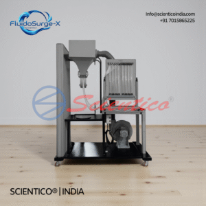
Axial Fan Compressor Demonstration Unit | FluidoSurge-X 196
A CE-certified compressor test rig for studying compression ratios, volumetric efficiency, and isothermal work input, manufactured by Scientico India to ISO 9001:2015 standards. Supplied with calibration certificate, operation manual, and complete export documentation. Designed for Fluid Mechanics laboratories in engineering colleges and technical institutions.
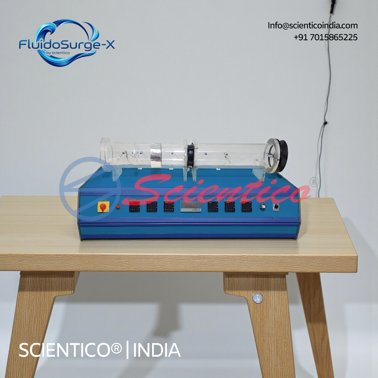
The Axial Fan Compressor Demonstration Unit FluidoSurge-X 196 is designed for experimental study of axial flow fan and compressor behavior. It enables investigation of characteristic variables such as flow rate, differential pressure, speed, and temperature. The unit supports stable, stationary airflow conditions with transparent intake and delivery sections. It is suitable for fluid mechanics and turbomachinery laboratory instruction.
Product Overview
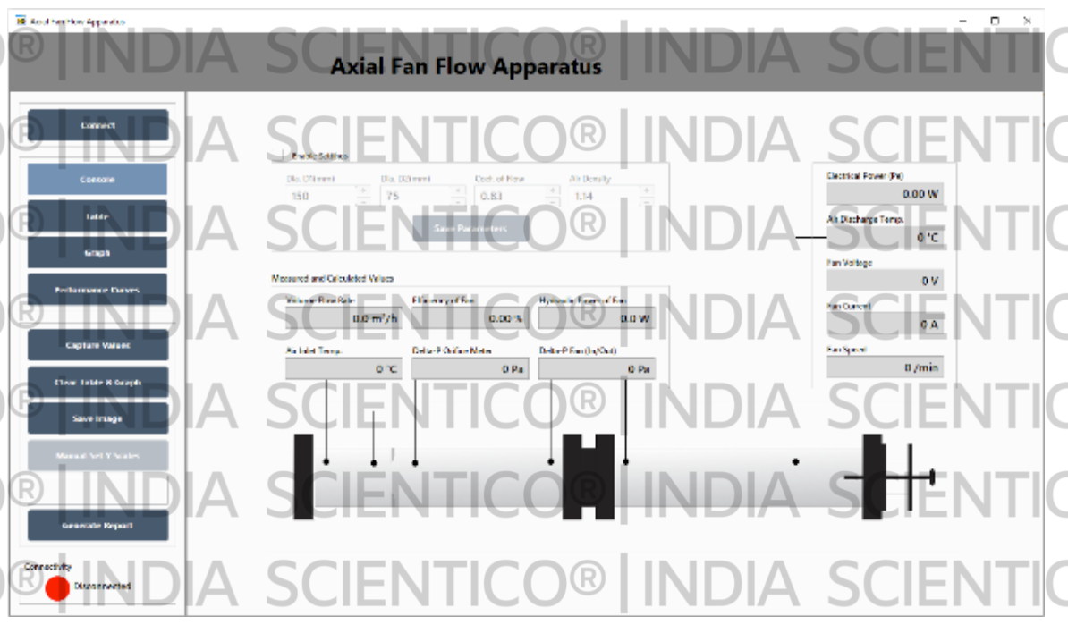
The SCIENTICO Axial Fan Compressor Demonstration Unit FluidoSurge-X 196 provides a controlled platform to study the operating behavior of an axial compressor or fan. A variable speed axial fan driven by an electric motor allows speed adjustment over a wide range, while a throttle valve regulates airflow and pressure. Integrated sensors measure pressure, differential pressure, temperature, and rotational speed. Optional data acquisition software enables visualization, curve plotting, and calculation of airflow from measured differential pressure.
Request Specifications & Pricing
CE-certified, ISO 9001:2015 compliant. Supplied to universities and institutions in 60+ countries.
WhatsApp: +91 701-586-5225 | Email: [email protected]
View Quality Certifications | FAQ — Shipping, Warranty, Lead Time
| Parameter | Specification |
|---|---|
| Model | FluidoSurge-X 196 |
| Type | Axial Fan Compressor Demonstration Unit |
| Application | Axial Fan and Compressor Studies |
| Intake Pipe Inner Diameter | 120 mm |
| Intake Pipe Length | 400 mm |
| Delivery Pipe Inner Diameter | 120 mm |
| Delivery Pipe Length | 400 mm |
| Fan Power Consumption | Up to 140 W |
| Nominal Speed | 9800 to 10000 RPM |
| Speed Control Range | 4000 to 10000 RPM |
| Maximum Flow Rate | Approx. 300 m³/h |
| Maximum Differential Pressure | Approx. 450 Pa |
| Differential Pressure Range | 0 to 2500 Pa |
| Temperature Range | -100 °C to 400 °C |
| Speed Measurement Range | 0 to 99999 RPM |
| Electrical Power Consumption | Less than 150 W |
Key Features-
-
Axial fan or compressor with wide variable speed control
-
Transparent intake and delivery pipes for stable flow and clear observation
-
Throttle valve for precise airflow and pressure adjustment
-
Integrated sensors for pressure, differential pressure, temperature, and speed
-
Digital display of measured electrical and mechanical parameters
-
Optional DAQ software for graphical visualization and data logging
Applications-
-
Study of operating behavior of axial fans and compressors
-
Recording characteristic curves of differential pressure versus flow rate
-
Analysis of speed effect on efficiency and delivery performance
-
Calculation of airflow from differential pressure measurements
-
Fluid mechanics and turbomachinery laboratory experiments
Construction & Design Details-
The unit features long transparent intake and delivery pipes to establish stable stationary airflow. An axial fan with variable speed drive is centrally mounted and coupled with a throttle valve at the delivery side. Measuring transducers are integrated for real time acquisition of pressure, temperature, and speed. The layout is designed for safe operation, clear visibility, and repeatable experimental conditions.
Export & Supply Capability-
SCIENTICO manufactures the Axial Fan Compressor Demonstration Unit FluidoSurge-X 196 for domestic and international supply. The equipment is suitable for export to engineering colleges, universities, and technical training institutes. Standard packing, interface module, cabling, and documentation are provided with each unit.
Q1. What type of experiments can be performed using this unit?
It supports axial fan and compressor characteristic studies, including pressure versus flow and speed effects.
Q2. How is airflow controlled during experiments?
Airflow is controlled using a throttle valve installed at the end of the delivery pipe.
Q3. What parameters are measured by the unit?
Differential pressure, temperature, rotational speed, voltage, and current are measured.
Q4. Is data acquisition software included as standard?
Data acquisition software is available as an optional accessory.
Q5. What is the benefit of transparent intake and delivery pipes?
They help achieve stable flow conditions and allow visual observation during experiments.
Explore Related Equipment
Discover more mechanical engineering lab equipment including testing systems, experimental setups, and training models designed for academic and industrial applications.
The Refrigeration System with Two-Stage Compression PolarX – 532 is designed for the generation of particularly low temperatures. This Refrigeration System with Two-Stage Compression links two compressors in series, each operating at a low pressure ratio, to overcome the drop in volumetric efficiency that occurs at high pressure ratios.
Product Overview Large pressure differences between the evaporator and condenser are necessary to reach very low temperatures. Since a compressor’s volumetric efficiency drops sharply at high pressure ratios, this Refrigeration System with Two-Stage Compression uses two compressors linked in series, each with a low pressure ratio. This allows the low pressure stage compressor to be sized more advantageously, since its large specific volume requires higher capacity at lower drive power.
Intercooling between the low pressure and high pressure compressors (LP and HP) further increases compression efficiency by bringing the HP compressor’s outlet temperature down to safe levels. The IRC-1909 equipment employs injection intercooling. The receiver injects a small quantity of liquid refrigerant into the LP compressor’s outlet line. As this liquid refrigerant evaporates, it cools the intake gas for the HP compressor.
An add-on heat exchanger in the injection cooler can increase the super cooling of the liquid refrigerant upstream of the expansion valve. This, in turn, increases the evaporator’s capacity. Valves allow the heat exchanger for refrigerant super cooling or the injection intercooling to be switched off, demonstrating the impact of each on the system.
Sensors record and display all relevant measured values. Simultaneous transmission of measurements to the optional programme enables real-time analysis and representation of the process in the p-h diagram. Two flow meters display the volumetric flow rates for the intercooling and the total volumetric flow rate.
The Reverse Cycle Refrigeration & AC Training Unit PolarX – 536 operates two evaporators on a single compressor using an evaporator pressure regulator. This Reverse Cycle Refrigeration & AC Training Unit demonstrates both refrigeration and air conditioning concepts in a single apparatus.
Product Overview The condensing unit of this Reverse Cycle Refrigeration & AC Training Unit has an air-cooled condenser, a liquid receiver, and a high starting torque motor with an integrated winding protector. A water-cooled condenser features an automated condenser pressure regulator. Both the static and forced air evaporators contain a copper tube coil block with fins.
Hand valves are used to select the Flow Controls. This group includes the automatic expansion valve, the internal and external equalized thermostatic expansion valves, and the capillary tube. A solenoid reversing valve operates the unit in reverse cycle. An evaporator pressure regulator allows the two evaporators to run at various pressures and temperatures.
Controls include a high pressure switch, low pressure switch, low pressure gauge, and high pressure gauge. An electrical control box mounted on the front panel houses on/off switches for the evaporator and condenser, a reverse cycle switch, an overload, and an earth leakage circuit breaker for protection against earth leakage.
The unit is mounted in a steel frame with stainless steel base and back panels.
The Hermetic Compressor Fault Simulator Trainer PolarX – 548 teaches the electrical connection, start-up, and operation of refrigerant compressors. This Hermetic Compressor Fault Simulator Trainer also covers essential safety considerations when working with mains voltage.
Product Overview Connecting electrical components for the start and operation of refrigerant compressors is a common task in the refrigeration industry. The IRC-1914 equipment makes it possible to learn these concepts and skills. All components are operated and tested with mains voltage to ensure high practical relevance.
The electrical parts required to start and run the refrigerant compressor are organized for easy visibility. The electrical connection of individual components is made with cables via lab jacks. The capacitor and start-up relay, for example, are components required to start the motor. The front panel’s circuit schematic makes it simple to allocate the various parts.
The pressure switches on the intake and delivery sides of the compressor can be checked using the refrigeration circuit with the compressor and receiver. Valves are used to set the pressure, and a pressure switch is tripped. Two manometers make it possible to monitor the pressure curve. If one of the pressure switches trips, the compressor’s current supply is cut off. Other standard safety chain parts, such as automatic fuses and circuit breakers, are also wired and checked as part of this Hermetic Compressor Fault Simulator Trainer.
The Automotive Air Conditioning Trainer PolarX – 544 replicates a vehicle’s air conditioning system used to cool the car’s interior. This Automotive Air Conditioning Trainer operates on the recirculating air principle, aspirating air from the interior and propelling chilled air back into the cabin via fan.
Product Overview A compressor, a condenser with fan, and an evaporator acting as an air cooler with a three-stage fan and expansion valve make up the refrigeration circuit used to produce cold air in this Automotive Air Conditioning Trainer. All system parts reflect common aspects found in automotive technology. For example, the air cooler with the three-stage fan is fitted with the normal air vents seen inside a car, bringing the trainer close to real-world practice.
The trainer runs on a standard automotive 12VDC power supply. The system also includes the ability to lock the ignition. The compressor is driven by an electric motor using a magnetic contact and a V-belt. A frequency converter allows variable adjustment of the motor’s and compressor’s speed, imitating the drive via the vehicle engine.
Pressure, temperature, flow rate, and the compressor’s power consumption are among the significant characteristic factors displayed. Eight connectable faults have been installed specifically (optional). The system is especially effective for teaching motor mechanics. Comprehensive course materials outline the fundamentals and offer a step-by-step walkthrough of the experiments.
The Universal Pumping Unit PolarX – 528 is engineered for versatile and efficient fluid handling applications. This Universal Pumping Unit integrates a high-efficiency pump with multiple monitoring and control components to provide precise and reliable fluid management.
Product Overview Designed for optimal performance and ease of use, this Universal Pumping Unit is ideal for various industrial and laboratory applications. It offers real-time data display and adjustable parameters to ensure operational accuracy and efficiency.
The frame is constructed from high-strength aluminum profiles, ensuring a lightweight yet robust structure that provides both durability and ease of handling. Bakelite is used for various panel components, offering excellent electrical insulation properties and resistance to heat. This makes it ideal for components exposed to varying temperatures and electrical components. A process flow diagram on the front of the panel describes the components involved in the apparatus and the process path followed by fluid.
The pump is a high-efficiency centrifugal pump with low power requirements. The suction and discharge nozzles connect to the respective fluid inlets and outlets, and all connections must be secure. Adjustable feet stabilize the unit on uneven surfaces and ensure proper alignment. Each foot can be adjusted individually to level the unit, accommodating different installation environments and maintaining operational stability.
The Air Conditioning Lab Unit PolarX – 556 examines how each part of an air conditioning system works and what effect it has on room air conditions. This Air Conditioning Lab Unit changes the air’s flow velocity, temperature, and humidity to meet the requirements of a desired room climate.
Product Overview In many daily situations, the condition of ambient air does not meet requirements, for instance in a tropical greenhouse, the production of delicate components, or even comfortable offices. This Air Conditioning Lab Unit includes all elements utilized in building services engineering, with special consideration given to the use of original parts.
Air coolers (direct evaporators with condensing units), steam humidifiers, fans, air preheaters, and reheaters are placed in an open air duct. These elements can be turned on or off individually. The effect of each individual component on the conditioning of air is as interesting as the effect of any combination of components.
Prior to and following each stage, sensors record the air’s temperature and humidity, along with the refrigerant’s pressure and temperature. Measured values can be shown on digital displays. A DAQ system also allows immediate transmission of measured values to a PC (optional), though data gathering software is not required. Well-structured instructional material sets out the fundamentals and provides a step-by-step guide through the experiments.
The Recirculating Air Conditioner Trainer PolarX – 560 shows a complete air conditioning system with an air duct and climate chamber through a clear, transparent design. This Recirculating Air Conditioner Trainer supports training in air conditioning technology, a key topic in building services engineering.
Product Overview Air conditioning technology has a significant impact on how engineers and skilled personnel are trained. The major elements of this Recirculating Air Conditioner Trainer are the air cooler with a condensing unit, fan, steam humidifier, and air heater. Air distribution in the system is managed by three motorized ventilation flaps.
The climatic chamber contains two different heat sources, wet and dry. Temperature and relative humidity are detected and digitally displayed at relevant locations in the air duct. Two manometers, thermocouples at relevant points, and a flow meter provide the necessary measurements for the refrigeration circuit.
Manual control is used to operate the air conditioning system. A key feature is that the system is fully ready for various automation solutions, so the user can focus on the important topic during a lesson. Available solutions include representation of the circuit in the p-h diagram, effect of a cooling load (dry and wet), mixing different air flows, and representation in the psychometric chart for humid air.
The Domestic Refrigeration Training Unit PolarX – 564 enables basic investigations in the field of refrigeration. This Domestic Refrigeration Training Unit includes an evaporator, a capillary type expansion device, a condenser with fan, a closed refrigeration circuit with compressor, and a door for the refrigerated chamber.
Product Overview A fan in the refrigeration chamber of this Domestic Refrigeration Training Unit enables an even distribution of temperature. The refrigeration chamber’s heater simulates a cooling load. For the compressor’s delivery and intake sides, the circuit has a pressure switch.
Gauges and sensors measure all relevant values, which are displayed on digital displays. The user can record measured values in a data recording software (optional), allowing for easy analysis and representation of the process in the p-h diagram. The software also shows important process data, such as the refrigeration capacity and the performance coefficient (optional).
Well-structured instructional material sets out the fundamentals and provides a step-by-step guide through the experiments.
The Building Management System Trainer PolarX – 568 is a lab scale trainer built to demonstrate intelligent control of climate, humidity, pressure, and fluid flow in modern buildings. This Building Management System Trainer uses simulated feedback signals instead of large scale field devices, making it suitable for hands on laboratory experiments in building automation.
Product Overview
Modern homes, hotels, and office buildings rely on intelligent unit management to handle climate controlling, humidity controlling, temperature managements, fluid controlling for heating and cooling applications, pressure managements, and access control managements. The Building Management System Trainer PolarX – 568 replicates these functions on a small lab scale model.
Different sensors on the trainer supply input signals to an advanced intelligent controller. These signals include temperature, humidity, pressure, flow, and access control inputs. Each controller manages its output according to programmable parameters linked to the building management function.
Instead of using physical large scale components and multiple output devices, the trainer uses simulated feedback signals. A heater is used for heating. Fluid flow is simulated as cold water to the evaporator. A humidifier is used for humidity control. An air blower is used for pressure control. A range of experiments can be performed for all the applications described above.
The Plastic Bending of Beams FortiTestX-46 is a structural mechanics laboratory unit for demonstrating plastic bending theory and collapse load behaviour in mild steel beams. This plastic bending of beams apparatus provides two end supports configurable as simple supports or rigid fixed ends, with a fine screw jack and integral 500 N load cell applying a single point load. Beam deflection is measured using a vernier gauge across both elastic and plastic deformation regions.
Product Overview
The Plastic Bending of Beams FortiTestX-46 enables experimental investigation of beam behaviour beyond the elastic limit, demonstrating the increase in bending moment capacity due to end fixity and redundancy. Two end supports are provided: one is fixed in position and the other allows horizontal travel to accommodate beam deformation during loading. Both supports can be configured as simple supports using knife edges, or as fully fixed ends using clamp plates that restrict end rotation. A fine screw jack mechanism with an integral load cell applies a controlled single point load of up to 500 N to the test beam. Load cell output and vernier gauge deflection readings connect to an external display unit, sold separately. Three fully annealed mild steel test beams are supplied, each 860 mm long with an 8 x 8 mm cross-section. This plastic bending of beams unit demonstrates how additional load capacity is generated as the beam becomes redundant through end fixing, and allows measurement of the collapse load at which a plastic hinge forms. All necessary assembly and operating tools are included. The apparatus must be used with a universal frame and stand, sold separately. Optional LabVIEW-based Software FX-46 enables data logging and results processing on any Windows operating system.
The Reaction of Beam Apparatus FortiTestX-45 is a benchtop structural mechanics unit for experimentally determining support reaction forces in a simply supported beam under various loading conditions. This reaction of beam apparatus uses two spring balances as supports for direct reaction force readout, with six movable load hangers enabling flexible load positioning along a 1000 mm beam. It validates the principle of equilibrium through direct comparison of measured and calculated support reactions.
Product Overview
The Reaction of Beam Apparatus FortiTestX-45 provides a straightforward experimental platform for studying beam support reactions, lever mechanics, and the principle of equilibrium. The apparatus centres on a 1000 mm long steel beam, 7 mm wide and 20 mm high, with 39 holes spaced at 25 mm intervals for precise load hanger positioning. Two spring balances, each with a 10 kg capacity and 50 g least count, act as the beam supports and provide direct readings of vertical reaction forces at each support. Six load hangers can be placed at any hole position along the beam, allowing a wide range of loading configurations including single point loads, multiple point loads, and asymmetric arrangements. The beam weight is 8.12 N and must be accounted for in calculations. By suspending the beam from the free-standing frame and attaching one end with spring balances, the same setup can be used to investigate loads and moments on a lever. This reaction of beam apparatus includes a 1000 mm measuring scale with 1 mm least count for accurate load position measurement. A technical manual is provided for both students and lecturers, covering theory, experiment protocols, and sample results. The full setup mounts on a benchtop frame with all accessories included.
The Buckling of Bars FortiTestX-44 is a structural mechanics laboratory unit for demonstrating and investigating elastic buckling behaviour in bars under compressive loading. This buckling of bars apparatus supports systematic variation of support conditions, cross-sections, materials, and additional shear forces, enabling full experimental verification of Euler’s buckling theory. Force and lateral deflection are measured directly through an integrated force gauge and two dial gauges.
Product Overview
The Buckling of Bars FortiTestX-44 provides a clear and controlled demonstration of elastic buckling in long slender bars subjected to compressive forces along their longitudinal axis. When a critical compressive force is reached, such bars lose stability and deflect laterally without material failure, remaining within the elastic stress zone. The apparatus includes a load mechanism for applying compressive forces to test bars that can be pinned or fixed at both ends depending on the buckling condition under investigation. A force gauge measures the applied compressive force, and a dial gauge records lateral deflection of the bar. Test bars of different materials and cross-sections are supplied: three steel bars (600 x 20 x 4 mm), two aluminium bars (600 x 25 x 6 mm), one aluminium circular bar (600 x 10 mm diameter), and one aluminium bar (600 x 15 x 2 mm). The effect of additional shear forces on buckling behaviour is demonstrated through a separate experiment in which a cable and weight apply a shear force at a joint along the buckling bar. This buckling of bars unit enables calculation of expected buckling forces using Euler’s buckling formula and graphical analysis of deflection against force. All components are organised in a storage system (1170 x 480 x 178 mm) with an approximate total weight of 30 kg. The complete experimental setup is housed in the structures test frame mounting frame.
The Young’s Modulus Apparatus FortiTestX-43 is a wall-mounted experimental unit for investigating the elastic elongation of metal wires under tensile loading. This Young’s modulus apparatus enables determination and verification of the modulus of elasticity for steel, aluminium, brass, and copper wire specimens, with elongation measured by a vernier gauge at 0.02 mm graduation. It covers the relationship between wire elongation, applied load, wire diameter, and material properties within a single compact wall-mounted setup.
Product Overview
The Young’s Modulus Apparatus FortiTestX-43 is fixed to a wall-mounted carrier from which wire specimens are suspended. The bottom ends of the wires are secured using two sliders. A traverse connects the wires at their lower ends and distributes applied load evenly across the specimens. Weights are placed on the traverse to load the wires in direct tension. Wire elongation resulting from the applied tensile force is measured using a moment lever fitted with a vernier gauge, providing a displacement range of 100 mm at 0.02 mm graduation. Wire specimens are available in four materials: steel, aluminium, brass, and copper. Each wire is 1000 mm in length with a diameter ranging from 1 to 2 mm. Experiments investigate elastic elongation as a function of applied load, wire diameter, and material, and enable direct determination and verification of the modulus of elasticity for each material. This Young’s modulus apparatus is suited to undergraduate engineering and materials science laboratory programmes requiring hands-on measurement of fundamental elastic material properties.
The Frame Deflections and Reactions FortiTestX-35 is a structural mechanics laboratory unit for investigating vertical and horizontal reaction forces and sway deflection in portal frames under load. This frame deflections and reactions apparatus includes two aluminium alloy portal frames, one with a uniform cross-section and one with a non-uniform leg, enabling direct comparison of structural behaviour across both configurations. Load cells connected to a Digital Force Display measure support reactions, while a digital deflection indicator records sway at the top of the frame.
Product Overview
The Frame Deflections and Reactions FortiTestX-35 mounts to a test frame and provides a complete experimental platform for studying portal frame behaviour under applied loading. Two rectangular aluminium alloy portal frames are supplied, both nominally 250 mm x 500 mm. One frame has a uniform cross-section throughout, with a 25 mm width and 6 mm breadth. The second frame has a non-uniform section, with one leg reduced to 4 mm breadth, producing a smaller second moment of area on that leg. Students clamp each leg of the portal frame to the test frame supports and apply loads using masses on a hanger at the top of the portal structure. Load cells at the supports connect to a Digital Force Display to measure vertical and horizontal reaction forces. A digital deflection indicator measures sway at the top of the portal frame. Using the measured moments and reactions, students plot bending moment diagrams and compare them against theoretical calculations. Sway direction and its causes are examined and discussed. The experiment is repeated with the second portal frame to compare the effect of the non-uniform section on structural behaviour. This frame deflections and reactions unit is supported by optional LabVIEW-based Software FX-35 for data logging and results processing on any Windows operating system. Virtual experiments within the software simulate hardware testing and extend available test conditions to include larger loads, uniform loads, and different test specimens. An optional Automatic Data Acquisition system enables automated collection and logging of experiment results.
Short Introduction
The Deformation of Frame FortiTestX-42 is a structural mechanics laboratory unit for investigating the deformation behaviour of steel frames under load. This deformation of frame apparatus covers both statically determinate and indeterminate conditions using U-shaped and S-shaped steel frames, with two dial gauges recording deflection at 0.01 mm resolution. It supports application of first-order elasticity theory, the principle of superposition, and the principle of virtual work within a single self-contained setup.
Product Overview
The Deformation of Frame FortiTestX-42 provides a comprehensive experimental platform for studying frame deformation, bending moment characteristics, and support reactions under varied loading conditions. The unit includes two steel frames: a U-shaped frame (600 x 600 mm) representing standard portal construction as found in hall structures, and an S-shaped frame (600 x 600 mm) for demonstrating the applicability of analytical methods to non-standard frame geometries. The U-shaped frame is clamped at one end; the opposite end can be left free for statically determinate analysis or fitted with a roller bearing for statically indeterminate investigation. Two sets of weights with movable hooks apply loads at adjustable positions along the frame. Two dial gauges with a 0 to 20 mm measuring range and 0.01 mm graduation record frame deformations under load. Bending moment characteristics are determined using first-order elasticity theory, the principle of superposition, and the principle of virtual work. The differential equation of the bent line is constructed from these characteristic curves and an integrals chart. Displacements and support forces at the movable bearing are calculated from the bent line and its derivatives. This deformation of frame unit stores all components in an organised storage system within a self-contained experimental frame. Optional frame variants FX-42A, FX-42B, FX-42C, and FX-42D extend the apparatus to portal frames with overhanging ends, redundant square frames, unsymmetrical portals, and square portal frames.
The Heat Exchanger Service Unit ThermoFlux – 7108 is a bench-mounted experimental control unit designed to provide hot and cold water circuits for the investigation and comparison of multiple heat exchanger types under parallel flow and counter flow conditions. This heat exchanger service unit is compatible with up to four interchangeable heat exchanger modules — plate type, concentric tube, shell and tube, and jacketed vessel — enabling systematic study of thermal energy transfer, mean heat transfer coefficients, and temperature curve plotting across different exchanger designs and flow configurations.
Product Overview
The Heat Exchanger Service Unit ThermoFlux – 7108 forms the central control and service element of a modular heat exchanger experimental system. The unit houses a stainless steel hot water tank of 50–60 litre capacity fitted with four electric heating resistances of 1.5 kW each (6 kW total), a PID digital temperature regulator, a K-type thermocouple for water temperature measurement, level switches to prevent dry-running of the heater, a stainless steel cover, and a draining valve. Hot water is circulated through the connected heat exchanger by a 0.75 HP centrifugal pump with a flow range of 0–29 litres per minute. Cold water is supplied from the laboratory mains or an optional chilling unit. Two flow meters — one for hot water and one for cold water — each cover a range of 1 to 7 litres per minute. A control valve regulates cold water flow, and a regulation pressure valve set at 0.6 bar prevents excess pressure in the exchanger. Four flexible connecting tubes allow rapid interchange of heat exchanger modules. The structural frame is constructed from anodised aluminium with an insulated HDF wood panel; all water-contact parts are manufactured from PVC, brass, copper, or stainless steel. A front panel diagram with laser-engraved labelling provides a schematic representation of the real unit layout. Temperature is monitored by one K-type thermocouple dedicated to the temperature controller (−100°C to 400°C) and six additional K-type thermocouples (−100°C to 400°C) distributed across the system. Measured values are displayed on digital indicators on the panel and can simultaneously be transmitted to a PC via USB/Ethernet when the DAQ option is selected. The heat exchanger service unit is designed to work exclusively as the service base; at least one heat exchanger module must be ordered separately to conduct experiments.
The Saturation Pressure ThermoFlux – 7069 is a bench-top laboratory apparatus designed to demonstrate the relationship between saturation pressure and boiling point temperature of water across a range of absolute pressures. Equivalent to a Marcet Boiler, the unit adds a throttling calorimeter and a pipe loop for condensate return, providing a comprehensive introduction to two-phase thermodynamics.
Students can generate saturation curves, compare results against published steam tables, and determine the dryness fraction of wet steam using the integrated throttling calorimeter. All sensors route to a USB port for optional PC data acquisition.
Product Overview
The Saturation Pressure ThermoFlux – 7069 heats pure water to its boiling point using a pair of cartridge heaters with variable power control. A sight glass on the front of the boiler allows direct observation of boiling patterns and continuous monitoring of water level.
Saturated steam leaving the top of the boiler travels around a pipe loop before condensing and returning to the base of the boiler for reheating. The operating range covers 0 to 8 bar gauge. The top limb of the pipe loop carries a K-type thermocouple, a temperature sensor, and an electronic saturation pressure sensor. A filling point at the bottom allows the loop to be filled with pure water.
A vapour offtake with an isolating valve diverts steam through a throttling calorimeter. As steam expands to atmospheric pressure, a second K-type thermocouple measures the post-expansion temperature, enabling calculation of the dryness fraction. A pressure relief valve is set to operate if pressure exceeds the working limit; a Bourdon gauge remains operational when power is disconnected.
All power supplies, signal conditioning, and circuitry are contained in an electrical console with current protection devices and an RCD for operator safety. Sensor readings are displayed on a common digital meter. All signals are routed to a USB port for optional connection to a PC using an optional parallel interface and educational software package.
The Combined Convection and Radiation ThermoFlux – 7073 is a small-scale laboratory accessory designed to introduce students to the principles of combined convection and radiation heat transfer from a horizontal heated cylinder. The unit operates in both free convection and forced convection modes, enabling analysis of the combined effects at varying surface temperatures and air velocities.
Measurement of the cylinder surface temperature and the electrical power supplied allows comparison of combined heat transfer effects with theoretical values. The dominance of convection at lower surface temperatures and the dominance of radiation at higher surface temperatures can be demonstrated directly.
Product Overview
The Combined Convection and Radiation ThermoFlux – 7073 comprises a heated cylinder mounted in a vertical air duct with a centrifugal fan at the base. The fan provides variable air flow over the cylinder, enabling study of free and forced convection conditions. A manually adjustable throttle plate permits the air velocity to be varied. On the computer-controlled unit, the air flow is electronically adjustable over the range 0 to 10 m/s by a variable-speed fan; otherwise it is manually adjustable.
The heated cylinder uses a rod heater rated at 100 W at 24 V DC, with a diameter of 10 mm and a length of 70 to 80 mm. The surface of the cylinder is coated with heat-resistant paint that provides a consistent emissivity close to unity. The mounting arrangement for the cylinder in the duct is designed to minimise loss of heat by conduction to the duct wall. The air blower provides air velocity up to 15 m/s.
A K-type thermocouple attached to the wall of the cylinder at mid position measures the surface temperature under varying operating conditions. A K-type thermocouple in the outlet duct measures the ambient air temperature upstream of the heated cylinder. An air velocity sensor within the fan outlet duct measures the air velocity in the duct. Sensor readings enable determination of combined convection and radiation heat transfer coefficients and comparison with published theoretical values.
All sensor signals are available for optional connection to a PC using an optional DAQ software package developed in the National Instruments LabVIEW environment. A comprehensive instruction manual is included.
The Perfect Gas Law Apparatus ThermoFlux – 7077 is a small-scale bench-top unit designed for experimental investigation of the perfect gas law apparatus principles, covering the first law of thermodynamics and the pressure, volume, and temperature relationships for air. Two transparent vessels connected by a large-bore pipe and valve, together with an integral air pump, enable a range of gas expansion and compression experiments.
Air is used as the test gas. The pump can pressurize one vessel and evacuate the other simultaneously. Additional valves allow the vessels to be operated singly or in combination, including venting to atmosphere and controlled transfer between a pressurized vessel and an evacuated vessel.
Product Overview
The Perfect Gas Law Apparatus ThermoFlux – 7077 consists of two transparent vessels: a large vessel with an approximate volume of 18.5 litres and a smaller vessel with an approximate volume of 10.5 litres. The vessels are connected by a large-bore pipe and valve with an integral air pump. The pump pressurizes one vessel while evacuating the other.
Additional valves provide three operating configurations: vessels in isolation, venting to or from atmosphere, and a combined arrangement where the pressurized vessel vents into the evacuated vessel. This range of configurations enables direct observation of perfect gas law apparatus behaviour including transient pressure and temperature responses.
Fast-response thermocouple sensors are located in each vessel to record air temperatures. Individual pressure transducers record chamber pressures. Two pressure gauges, one per vessel, cover a range of -1 to 4 bar. Two temperature sensors, one per vessel, cover a range of -100 to 400°C. Pressure relief valves prevent over-pressurization in the pressurized vessel. Pressure switches limit operating pressures to safe levels.
The vessels and interconnecting pipework are constructed from impact-resistant plastic. A control box digitally displays air temperatures in both vessels. The unit supports optional continuous PC monitoring of pressure and temperature changes. The air pump is available in manual or optional computer-controlled versions.
The Nozzle Pressure Distribution ThermoFlux – 7103 is a laboratory apparatus for measuring pressure curves in convergent and convergent-divergent (de Laval) nozzles and for studying the actual flow of compressible fluids. The unit demonstrates nozzle pressure distribution across subsonic, supersonic, and shock wave velocity ranges using air as the working fluid.
Three interchangeable brass nozzles are provided: one convergent nozzle and two de Laval nozzles with short and long nozzle extensions. The unit also demonstrates the choking effect, where the mass flow rate ceases to increase upon reaching the critical pressure ratio.
Product Overview
The Nozzle Pressure Distribution ThermoFlux – 7103 uses compressed air as the working compressible fluid. Air flows through a selected nozzle and is accelerated, with the nozzle pressure distribution recorded in the direction of flow over several measuring points. The air pressure upstream and downstream of the nozzle can be independently adjusted.
A compressed air regulator with a control range of 0 to 8.6 bar adjusts the upstream supply pressure. A needle valve on the flow meter adjusts the back pressure downstream of the nozzle. The unit accepts a maximum compressed air supply of 10 bar with an approximate air consumption of 5 g/s.
Three brass nozzles with pressure measurement points are included: one convergent nozzle for subsonic investigations, one de Laval nozzle with a short nozzle extension, and one de Laval nozzle with a long nozzle extension for supersonic and shock wave studies. Instruments include a manometer and a digital temperature display upstream and downstream of the nozzle, as well as a rotameter for flow measurement.
Temperature is measured across the range -100 to 400°C. Pressure is measured at 10 points across the range -1 to 9 bar. Flow rate is measurable up to 25 m³/h. Optional DAQ software in the National Instruments LabVIEW environment enables PC-based data recording, storage, and analysis.
The Thermal Expansion Apparatus ThermoFlux-26 is a precision laboratory instrument for determining the linear thermal expansion of brass, copper, and aluminium as a function of temperature. This thermal expansion apparatus uses a dilatometer method with a digital dial gauge to measure dimensional change in 500 mm expansion rods across three materials. Students investigate the direct relationship between temperature change, material properties, and change in length.
Product Overview
The ThermoFlux-26 is designed for quantitative measurement of linear expansion in metallic rods subjected to controlled temperature variation. Three expansion rods, one each in brass, copper, and aluminium, are each 500 mm in length. Temperature is applied via a heating system with a 2-litre tank capacity and a heating power range of 500 W to 1,000 W. Dimensional change is measured using a digital dial gauge with a range of 0 to 20 mm and a resolution of 0.01 mm, providing precise tracking of rod elongation at each temperature step.
The apparatus supports determination of linear expansion coefficients for each material, investigation of the relationship between change in length and overall rod length, and study of equilibrium spacing and thermal capacity. Results are obtained directly from the dial gauge readings against measured temperature.
An optional DAQ software package, developed in the National Instruments LABVIEW environment, is available for automated data acquisition and analysis. When the software option is selected, a set of electronic sensors is included. The software is compatible with any Windows operating system.
The Thermal Conductivity Apparatus ThermoFlux-25 is a laboratory instrument for measuring heat flow across a consistent 100°C temperature differential through five common building and insulation materials. This thermal conductivity apparatus uses a steam chamber as the hot reservoir and a block of ice as the cold sink, with the rate of ice melt into water serving as the quantifiable measure of heat transfer through each test sample. Students determine thermal conductivity values for Bakelite, wood, aluminium, Sheetrock, and Masonite using identical sample geometry across all tests.
Product Overview
The ThermoFlux-25 operates on a straightforward principle: a test sample is clamped between a steam chamber on one side and a block of ice on the other. The steam chamber maintains a constant temperature, creating a 100°C differential across the sample. Heat flows from the steam, through the test material, and into the ice. The rate of ice melting, collected as water into a glass beaker, provides a direct, measurable indicator of the thermal conductivity of each material.
Five sample materials are supplied: Bakelite, wood, aluminium, Sheetrock, and Masonite. Each sample is 100 x 100 mm in face dimension and 5 mm thick. Wood, Masonite, and Sheetrock samples are covered with a thin aluminium sheet for waterproofing, ensuring effective thermal contact during experiments. The steam reservoir is fabricated from stainless steel with a 2-litre capacity and is positioned high above the lab table to eliminate risk of heat damage to the work surface. Meltwater flows directly into the measuring beaker, keeping the lab table free of spillage.
Two steel ice molds, each with a capacity of 300 to 400 ml, are supplied for preparing ice blocks. A glass beaker of 500 ml capacity collects meltwater for measurement. A measuring scale with a range of 0 to 100 N and a resolution of 0.1 N is included. The complete assembly is mounted on a stand with insulating pads.
An optional small steam generator (ThermoFlux-25) is recommended for operation. Optional DAQ software developed in the National Instruments LABVIEW environment is also available, compatible with any Windows operating system. Electronic sensors are included when the software option is selected.
The Small Steam Generator ThermoFlux-24 is a compact, variable-power laboratory heat reservoir designed to provide continuous steam at a constant temperature. This small steam generator boils 3/4 litre of water in ten minutes and delivers continuous steam output at up to 2.5 kg/h. Dual steam ports, a 1-litre water capacity, and variable power from 0 to 3,000 W make it a practical and flexible steam source for laboratory thermal experiments.
Product Overview
The ThermoFlux-24 is built for reliable, consistent steam supply in laboratory settings. It holds 1 litre of water and heats it using an internal electric heater, eliminating any open flame or exposed coil hazard. Variable power adjustment from 0 to 3,000 W allows the user to control steam flow rate to match experimental requirements. Continuous steam output reaches up to 2.5 kg/h.
Two steam ports allow the unit to supply two laboratory groups simultaneously from a single generator. A rubber stopper provides a tight seal and incorporates a safety pressure release function. A low water warning light alerts the user before the water level becomes critically low. An extra-wide base provides stability and resistance to tipping during operation. An included baster allows safe removal of hot water during experiments.
This small steam generator is suitable as a heat reservoir for use with compatible laboratory apparatus, including the Thermal Conductivity Apparatus ThermoFlux-25.
The Extended Surface Heat Transfer Module ThermoFlux – 7049/4 is a laboratory module for investigating temperature distribution and heat transfer along a cylindrical pin fin under combined free convection and radiation conditions. This extended surface heat transfer module uses a 350 mm brass pin fin with 9 thermocouple positions and a 100 W heater to enable direct measurement and comparison with theoretical fin analysis. Students determine thermal conductivity of the rod material and calculate combined convective and radiative heat transfer from the fin surface.
Product Overview
The ThermoFlux – 7049/4 centres on a cylindrical brass pin fin element, 10 mm in diameter and 350 mm in length, instrumented with 9 thermocouple positions along its length. The fin is heated at its base by a 100 W heater. Temperature readings at each of the 9 positions along the rod allow students to plot the full axial temperature distribution and compare measured profiles directly against theoretical predictions from analytical fin equations.
Extended surfaces, commonly referred to as fins, transfer heat from a body by combining conduction within the solid with convection and radiation from its outer surface to the surrounding environment. Pin fins, characterised by a high length-to-diameter aspect ratio, are widely used in cooling systems for electrical appliances such as computer power supplies and substation transformers, as well as in engine cooling applications. The ThermoFlux – 7049/4 replicates this configuration at laboratory scale for structured experimental analysis.
Three core experiments are supported: measurement of axial temperature distribution with theoretical comparison, determination of thermal conductivity of the brass rod material, and calculation of combined free convection and radiation heat transfer from the extended surface with comparison to theoretical predictions.
The module requires the Heat Transfer Service Unit ThermoFlux – 7049 for operation.
The Radiation Heat Transfer Module ThermoFlux – 7049/3 is a laboratory module for demonstrating and verifying the fundamental laws governing thermal radiation heat transfer. This radiation heat transfer module provides an electrically heated radiant source rated at 300 W with a maximum temperature of approximately 460°C, a set of seven metal specimens across three materials, and an aperture plate assembly for structured experimental investigation. Students verify the inverse square law, Stefan-Boltzmann Law, Kirchhoff’s Law, emissivity, absorptivity, and geometric view factor relationships through direct measurement.
Product Overview
The ThermoFlux – 7049/3 is designed to illustrate how thermal radiation, as a mode of heat transfer distinct from conduction and convection, behaves according to established physical laws. A 300 W electrically heated plate serves as the radiant source, reaching a maximum temperature of approximately 460°C. A radiometer measures radiation intensity at the specimen surface. Seven metal specimens in three materials, stainless steel, aluminium, and copper, each measuring 135 x 145 mm, provide a range of surface finishes and coatings for comparative emissivity and absorptivity measurement.
The specimen set covers bright, matt anodized, nickel-plated, and high-temperature painted surfaces. Stainless steel specimens oxidise over time due to high operating temperatures, providing an additional surface condition for study. Aluminium specimens are supplied in three variants: matt anodized on both sides, painted on both sides with high-temperature paint, and matt anodized with one painted side. Copper specimens are supplied in two variants: nickel-plated and bright, the latter also oxidising over time.
An aperture plate assembly, consisting of two plates with insulation on one side, is used in view factor experiments. The insulated surface faces the heated source during experiments to control radiation geometry. All experiments compare measured results against theoretical predictions from the relevant radiation equations.
The module requires the Heat Transfer Service Unit ThermoFlux – 7049 for operation.
The Linear Heat Conduction Module ThermoFlux – 7049/1 is a laboratory module for the experimental investigation of one-dimensional, steady-state and unsteady-state linear heat conduction through solid materials. This linear heat conduction module uses an insulated brass heated section, a water-cooled brass cold section, and four interchangeable test specimens instrumented with nine thermocouples to enable direct measurement of temperature distribution, thermal conductivity, contact resistance, and the Overall Heat Transfer Coefficient across single and composite material configurations. A 100 W heater provides controlled thermal input, with power measured and controlled by the Heat Transfer Service Unit.
Product Overview
The ThermoFlux – 7049/1 consists of a cylindrical brass heated section and a matching brass cold section, each 25 mm in diameter, mounted on a bench support frame. The heated section contains a 100 W electric heater. The cold section is water-cooled using standard laboratory tap water. Both sections are fitted with three thermocouples at equal intervals along their length, providing six of the nine total measurement points. The remaining thermocouple positions are located in the interchangeable intermediate test sections.
Four interchangeable test sections are supplied, each 25 mm in diameter and 30 mm in length: a brass test section with temperature sensor array, a stainless steel test section, and an aluminium test section. A separate brass test section with a reduced diameter of 16 mm and 30 mm length is also included for cross-sectional area variation experiments. Any intermediate section can be clamped between the heated and cold ends, or the two ends can be clamped directly together. Thermal paste is supplied for interface contact optimisation.
All nine thermocouples connect directly to the Heat Transfer Service Unit, with temperature readings displayed on its digital panel meter. Heater power is controlled and measured through the same unit. This linear heat conduction module supports eight structured experiments covering steady-state and unsteady-state conduction, Fourier Rate Equation application, composite wall analysis, thermal conductivity determination for metals and poor conductors, contact resistance demonstration, cross-sectional area effects, and engineering application exploration.
The module requires the Heat Transfer Service Unit ThermoFlux – 7049 for operation.
The Heat Transfer Service Unit ThermoFlux – 7049 is a fully instrumented bench-top service unit designed to power, control, and monitor the full range of ThermoFlux heat transfer modules. This heat transfer service unit provides regulated and adjustable DC power output, a 9-point Type K digital temperature indicator with a range of 0 to 800°C, PID-configurable heat controller, and digital meters for voltage and current. The modular design supports continuous expansion with compatible optional modules and an optional LABVIEW-based data acquisition system.
Product Overview
The ThermoFlux – 7049 serves as the central instrumentation and power platform for a range of optional heat transfer modules covering linear conduction, radial conduction, extended surface heat transfer, unsteady-state heat transfer, and radiation heat transfer. All instrumentation is standardised across modules, allowing the same service unit to power and monitor any connected module without reconfiguration.
The unit provides regulated and adjustable DC power suitable for all optional modules, with multiple auxiliary power outlets for additional equipment. A 9-point digital temperature indicator accepts Type K thermocouples and measures across a range of 0 to 800°C, with 10 temperature measurement channels each spanning -100 to 400°C. A heat controller is configurable in PID mode for precise thermal regulation. Digital meters cover voltage from 0 to 500 V and current from 0 to 20 A.
Internal electronic and mechanical safety devices are built into the unit, making it suitable for unsupervised student operation. An optional autonomous pilot unit with computerised control software is available for advanced operation. Optional DAQ software, developed in the National Instruments LABVIEW environment and compatible with any Windows operating system, enables detailed data collection and real-time monitoring. A set of electronic sensors is included when the software option is selected.
The unit is supplied with one set of thermocouples. Five optional modules are available: Linear Heat Conduction Module ThermoFlux – 7049/1, Radial Heat Conduction Module ThermoFlux – 7049/2, Radiation Heat Transfer Module ThermoFlux – 7049/3, Extended Surface Heat Transfer Module ThermoFlux – 7049/4, and Unsteady State Heat Transfer Module ThermoFlux – 7049/5.
The Bubble Point Calculation Unit ThermoFlux-27 is a standalone laboratory unit for studying and comparing the bubble point and dew point phenomena through direct experimentation. This bubble point calculation unit enables students to separate a solvent from a solution using both the bubble point method and the dew point method on the same apparatus. A coil condenser, glass and stainless steel feed and vapour separation tanks, and three temperature measurement channels provide a complete platform for comparative vapour-liquid equilibrium experiments.
Product Overview
The ThermoFlux-27 is designed as a self-contained unit for performing comparative experiments on bubble point and dew point behaviour. A boiler heats the feed solution, with heater temperature controlled by a dedicated temperature controller and heating power adjustable via a regulating knob across a range of 0 to 3 kW. Boiler vapour temperature and vapour separation temperature are each measured independently, with three temperature measurement channels covering -100 to 400°C.
The feed tank has a capacity of approximately 3 litres and is constructed from glass and stainless steel. The vapour separation tank has a capacity of approximately 0.5 litres, also in glass and stainless steel. A coil-type glass condenser, 780 mm in height, condenses the separated vapour back to liquid. Cooling water flow rate to the condenser is adjustable and measured within a range of 1 to 7 litres per minute. System pressure is monitored by a pressure gauge with a range of 0 to 4 bar.
The unit supports two structured experiments: solvent separation from a solution using the bubble point method and solvent separation using the dew point method. Both experiments are conducted on the same apparatus, enabling direct comparative analysis of the two separation approaches.
The Joule-Thomson Apparatus ThermoFlux-28 is a laboratory and demonstration unit for the experimental determination of the Joule-Thomson coefficient of real gases, specifically CO2 and N2. This Joule-Thomson apparatus is equipped with a heat exchanger, a plastic-coated glass tube with throttle body, two Pt-100 temperature sensor measurement points, and a copper coil heat exchanger of 37.5 m length across 132 coils. The unit operates in an overpressure range of 0 to 10 bar and functions at room temperature, enabling direct measurement and comparison of real gas expansion behaviour against ideal gas theory.
Product Overview
The ThermoFlux-28 measures the Joule-Thomson coefficient by expanding gas across a frit from the overpressure shown on the manometer to ambient pressure. The heat exchanger reheats the gas that has been cooled at the pressure-reducing valve of the gas pressure cylinder back to ambient temperature, bringing the system to a consistent starting temperature before each expansion measurement. This controlled pre-conditioning ensures repeatable results across successive experiments.
The glass section of the unit is enclosed in a transparent plastic case to protect against glass splinters during operation. The plastic-coated glass tube, 250 mm in length and 46 mm in diameter, houses the throttle body and two Pt-100 temperature measurement points. A frame with a pressure gauge and a spiral of copper capillary tube forms the heat exchanger assembly. The copper coil is 37.5 m in total length across 132 coils. The pressure gauge covers 0 to 10 bar with a graduation of 0.05 bar. The digital temperature measuring instrument displays temperature to 0.1°C resolution in differential measuring mode.
The unit operates in an overpressure range of up to 1 bar in standard use and is fundamentally a room-temperature apparatus. Ten structured experiments cover the Joule-Thomson coefficient for CO2 and N2, real gas behaviour, intrinsic energy, Gay-Lussac theory, the throttling phenomenon, the Van der Waals equation, Van der Waals forces, the inverse Joule-Thomson effect, and inversion temperature.
Optional DAQ software (ThermoFlux-28), developed in the National Instruments LABVIEW environment, is available for automated measurement and calculation, compatible with any Windows operating system. A set of electronic sensors is included when the software option is selected.
The Plate Type Heat Exchanger ThermoFlux – 7108/1 is a laboratory heat transfer unit for studying heat exchange between hot and cold water through a plate heat exchanger under parallel flow and counter flow configurations. This plate type heat exchanger features stainless steel sealed plates, an anodized aluminium structure, and a front panel with a process diagram matching the real unit layout. Hot and cold water temperatures are measured at both inlet and outlet, with a pump for hot water circulation and a cold water valve for flow type selection.
Product Overview
The ThermoFlux – 7108/1 is built around a plate heat exchanger formed by stainless steel sealed plates arranged in alternate channels. Hot and cold water pass through these alternate channels, transferring heat across the plate surfaces. The unit provides two input ports for hot and cold water and two output ports for hot and cold water, with a maximum flow capacity of 30 m³/h. Cold water is supplied from an external source such as a hydraulic bench. A cold water valve selects between parallel flow and counter flow configurations. A pump circulates hot water through the exchanger.
The plate heat exchanger operates across a maximum working pressure of 30 bar and a maximum working temperature of 120°C. Minimum working temperature is 4°C for water and -30°C for gases. The exchanger accommodates a maximum of 10 or more plates, an internal circuit capacity of more than 0.250 litres, an external circuit capacity of 0.250 litres, and a total heat transfer area of more than 0.21 m².
The unit structure is anodized aluminium with a panel in HDF sheet. All main water-contact elements are fabricated from stainless steel or brass. The front panel displays a process diagram with a layout corresponding directly to the positions of the real components on the unit. Instruments for control and monitoring are provided throughout.
The Unsteady State Heat Transfer Module ThermoFlux – 7049/5 is a dedicated laboratory module designed for in-depth investigation of temperature variation over time and heat flow dynamics within solid shapes subjected to sudden surface heating. This unsteady state heat transfer module uses a 5-litre insulated stainless steel water bath, an integral flow duct, and an external circulating pump to maintain uniform bath temperature. Seven solid specimens in three geometric shapes, each with a built-in centre temperature sensor, enable direct transient thermal analysis across different materials and dimensions.
Product Overview
The ThermoFlux – 7049/5 centres on a 5-litre insulated stainless steel water bath fitted with a top plate and mounting for a solid shapes holder. An integral flow duct and external water circulating pump, controlled by a valve for flow rate adjustment, ensure uniform temperature distribution throughout the bath. A thermostat allows the bath to be set and maintained at a nominally constant temperature before experiments begin.
The heating element is rated at 300 W and incorporates internal thermal protection that automatically cuts power if the heater is activated without sufficient water coverage. Users should avoid repeated exposure of the heater to dry-run conditions to prevent premature component failure.
Seven solid specimens are supplied, made from brass and stainless steel, in three geometric forms: solid sphere, rectangular slab, and long solid cylinder. Each specimen has a built-in temperature sensor at its centre, enabling direct measurement of transient temperature response at the core of each shape.
The control panel integrates all necessary wiring, temperature measurement, and digital indicators for effective monitoring during experiments. The module requires the Heat Transfer Service Unit ThermoFlux – 7049/5 for operation.
This unsteady state heat transfer module supports experiments using analytical transient-temperature and heat flow charts, the Lumped Thermal Capacitance method, and comparative thermal conductivity analysis across materials and shapes.
The Cross Flow Heat Exchanger ThermoFlux – 7078 is a laboratory-grade unit designed to enable students to investigate heat transfer rates by free and forced convection. This cross flow heat exchanger provides hands-on experimentation with interchangeable heating elements, adjustable airflow, and digital measurement display, making it a precise tool for thermal engineering studies.
Product Overview
The Cross Flow Heat Exchanger ThermoFlux – 7078 consists of a vertical air duct through which air is drawn by a radial fan. Three interchangeable heater elements, a pipe, a pipe bundle, and a finned pipe bundle, dissipate heat directly into the airflow. Each heater element operates at 500W. The heating power is adjustable, and the air flow rate is variable, allowing systematic investigation across different conditions.
Electronic sensors measure temperature, differential pressure, and power. All measured values are displayed digitally on the front-mounted instrumentation unit. Data can also be transferred directly to a PC. The flow rate, Reynolds number, and Nusselt number are calculated from sensor data. The temperature-time relationship and the dependence of the Nusselt number on the Reynolds number can be demonstrated graphically.
The heater insert in the pipe bundle configuration can be repositioned across different pipe rows to investigate the effect of flow arrangement on heat transfer performance.
The Dew Point Hygrometer ThermoFlux – 7089 is a laboratory trainer designed to enable students to measure air humidity using four different instruments simultaneously within a single climatic chamber. This dew point hygrometer supports direct comparison of psychrometric, hygrometric, and capacitive measurement methods, providing a comprehensive platform for humidity measurement studies.
Product Overview
The Dew Point Hygrometer ThermoFlux – 7089 is built around a climatic chamber with a transparent door. The chamber houses four humidity measurement instruments: a hair hygrometer with real hair, a hygrometer with synthetic fiber, a capacitive humidity sensor, and a wet and dry bulb thermocouple. All four instruments can be read and compared simultaneously under identical chamber conditions.
The chamber humidity is actively controlled in both directions. Humidification is achieved via an ultrasonic atomizer rated at 22 W with a low-water cut-off. Dehumidification is performed by a Peltier cooling element with a cooling capacity of 58 W at 50°C ambient temperature and a cooling surface of 1600 mm². A recirculation fan circulates air within the chamber to ensure uniform mixing.
Psychrometers operate on the principle of evaporation cooling, comparing ambient temperature with wet bulb temperature. Hair hygrometers use the property of specific fibers to expand with increasing humidity. The capacitive sensor measures changes in the dielectric constant of a layer caused by absorbed water molecules. All three principles are represented in this trainer, making it suitable for direct instrument comparison and methodology studies.
An optional Whirling Psychrometer (TH-3117-01) with a measuring range of -5 to 50°C and 1°C graduation is available as an accessory. Optional DAQ software is available for PC-based data acquisition.
The Recycle Loops ThermoFlux – 7089 is a bench-top laboratory apparatus designed to demonstrate recycle loop behaviour and enable mass and energy balances under both steady state and unsteady state conditions. This recycle loops unit models a typical heating arrangement from the chemical, food, and pharmaceutical industries, where product temperature is controlled by recirculating fluid through a plate heat exchanger configuration.
Product Overview
The Recycle Loops ThermoFlux – 7089 consists of a through pipe conveying water from a cold-water supply to a drain, with a loop of pipework connected between the supply and drain connections. The recycle loop incorporates a variable-speed gear circulating pump (12 lpm, 4 bar, 180 W) and a 0 to 3000 W electric heater with over-temperature protection. A pressure regulator with filter at the inlet minimizes the effect of fluctuations in the cold-water supply pressure.
Loop flow rate is variable from 0 to 7 l/min, and the passing flow of water is also variable from 0 to 7 l/min. The heater can be switched on or off to generate step changes for transient response investigation. A waste-free quick disconnection fitting enables a short pipe or a 1 L reservoir to be connected in series with the recycle loop to change the loop volume and demonstrate the effect of residence time. Different lengths of flexible tubing can also be connected in series for further residence time variation.
Water temperatures at the inlet, outlet, and within the recycle loop are measured by K-type thermocouples. Flow rates at the inlet, outlet, and corresponding loop locations are measured by miniature turbine-type flow sensors. Flow sensors at both inlet and outlet demonstrate that these two flow rates remain equal regardless of recycle rate. All power supplies and signal conditioning circuitry are housed inside the control panel. The console includes a digital meter displaying temperatures and flow rates. Signals can be sent to DAQ via LAN or USB port for PC connection. An RCD and appropriate current protection devices are fitted for operator protection.
The Steam Power Plant ThermoFlux – 7090 is a laboratory-sized steam power plant comprising a fire tube boiler, steam turbine, condenser, water treatment system, DC generator, instrumentation, turbine speed control, and fuel system. This steam power plant is designed to enable students to study boiler performance, turbine operation, power generation efficiency, and complete power plant cycle analysis in a structured laboratory environment.
Product Overview
The Steam Power Plant ThermoFlux – 7090 integrates all major components of a complete steam power cycle into a single bench-scale unit. The vertical fire tube boiler is constructed from SS 304, operates up to 7 bar, and is fired by an automatic on/off LPG/LNG or oil-fired forced draft burner with atomizer. Two high-pressure switches, one mechanical high-pressure safety device, and temperature safety controls by digital temperature controller and bimetallic switch are included. A mis-fire safety system is built into the burner.
The feed water system includes a mini RO unit, a soft water tank, a feed water pump, and digital temperature sensor display. Both automatic and manual operation modes are user-selectable. The fuel system includes a fuel tank and a fuel flow meter. The complete boiler assembly is packaged on a skid for easy installation.
The single-stage impulse axial turbine with Curtis wheel delivers a maximum continuous output of over 25 W and operates at speeds of approximately 18,000 to 30,000 rpm with atmospheric exhaust pressure. Turbine runner diameter is 55 to 75 mm. A water-cooled shell and tube condenser handles condensate recovery.
The DC generator is rated at 50 VA, self-excited or permanent magnet type, with an output of 24 to 220 VDC at 3000 rpm. Four 15 W load lamps are included. A voltmeter, ammeter, generator speed sensor, and indicator are fitted in the generation section. Speed sensors, steam inlet and outlet temperature sensors, and a steam inlet pressure gauge are included in the turbine instrumentation section.
An optional water tube superheater (gas fired) is available, along with a cooling tower, separating and throttling calorimeter, and steam lagging accessories.
The Two Stage Air Compressor ThermoFlux – 7092 is a laboratory trainer designed to enable students to study the operating characteristics and thermal behaviour of a two-stage reciprocating compressor with intercooling. This two stage air compressor is equipped with a water-cooled intercooler, orifice-type flowmeter, pressure vessels, and digital instrumentation across both compression stages, providing a complete platform for compressor performance and efficiency analysis.
Product Overview
The Two Stage Air Compressor ThermoFlux – 7092 consists of a two-cylinder V-arrangement reciprocating compressor with a water-cooled intercooler between the first and second stages. Air is drawn from atmosphere into an intake vessel, which stabilizes the intake pressure. An orifice-type flowmeter at the intake measures the incoming airflow rate. After the first stage of compression, air passes through the water-cooled intercooler, which stabilizes pressure by controlling temperature before feeding into the second stage. The second stage compresses the air and delivers it to a final storage pressure vessel.
The compressor operates at a power consumption of 2.2 kW with a variable speed of 0 to 900 rpm and an intake capacity of 200 L/min. The operating pressure is 12 bar with a maximum of 20 bar. The pressure vessel has a capacity of 200 L, an operating pressure of 8 bar, and a maximum pressure of 12 bar. It is fitted with a safety valve, control valve, and outlet silencer.
Sensors measure pressures and temperatures across both stages as well as electric power consumption. All measured values are shown on digital displays. Analogue pressure gauges are also provided for direct visual reference. Measured values can be transmitted to a PC via USB (optional). Safety devices including pressure relief valves and pressure switches are fitted throughout the trainer. The optional software enables recording of compressor characteristics and representation of the compression process in a p-V diagram.
The Nozzle Performance Study System ThermoFlux – 7094 is a fully instrumented laboratory unit designed to enable students to study nozzle performance as both a kinetic energy producer and a thrust producer using compressed air. This nozzle performance study system includes five interchangeable brass nozzles, a baffle plate, force measurement via flexion pipe deformation, and digital instrumentation for pressure, temperature, mass flow, and force across a wide range of pressure ratios.
Product Overview
The Nozzle Performance Study System ThermoFlux – 7094 is supplied with compressed air from a separate compressor at a maximum inlet pressure of 10 bar and an air consumption of approximately 5 g/s. Five brass nozzles are included: four convergent-divergent nozzles and one convergent nozzle. The convergent-divergent nozzles have a throat diameter of 2 mm, and the convergent nozzle has a diameter of 2.19 mm. All nozzle lengths range from 3.6 mm to 15.8 mm. The nozzles are designed to operate at different theoretical expansion ratios and can be exchanged rapidly.
The unit measures both the reaction force (thrust) of the fluid at the nozzle and the action force at the baffle plate. Force measurement is performed by deformation of a flexion pipe, with a measuring range of 0 to 5 N. The distance between the baffle plate and the nozzle is adjustable. Air intake is adaptable according to the experiment layout. A compressed air regulator with a control range of 0 to 10 bar adjusts the pressure downstream of the nozzle. A needle valve on the flowmeter adjusts the back pressure.
Instrumentation includes a manometer and digital temperature display upstream and downstream of the nozzle, as well as a flowmeter. Measuring ranges cover temperature (-100 to 400°C), pressure (2x 0 to 10 bar), mass flow (0.7 to 8.3 g/s), and force (0 to 5 N). Operating conditions can be varied rapidly to generate results across a wide range of pressure ratios. Optional DAQ software enables PC-based data acquisition in a LabVIEW environment.
Product Overview
The unsteady state heat transfer unit consists of a stainless steel water bath with an integral flow duct and an external water circulating pump. The bath has a capacity of approximately 30 liters. It is heated by a thermostatically controlled 3 kW electric heating element installed in the base of the bath. The thermostat allows the bath to be set to a nominally constant temperature before beginning the experimental procedure. The water bath can achieve temperatures upto 80oC. A variable-speed centrifugal pump circulates the water at a flowrate of upto 5 LPM with a head of 1m. The heating element incorporates internal thermal protection. Power is switched off if the heater is turned on when it is not covered by water. Repeatedly allowing the heater to overheat in this condition should be avoided because the heater will eventually fail. The control panel includes all necessary wiring, temperature measurements and digital indicators. Solid shapes are installed in a special holder at the center of the top cover of the testing water bath. The holder also has a temperature sensor that enters the water bath at the same time as the shape. Optional DAQ software is specially designed in the National Instrument™, LABVIEW™ environment. It measures and calculates the results of the apparatus. A set of electronic sensors is included while using the software. The software can run with any Windows™ environment.
The Air Flow Impulse Turbine ThermoFlux – 7095 is a standalone table-top laboratory unit designed to enable students to investigate the performance of a single-stage axial flow impulse turbine using compressed air. This air flow impulse turbine is equipped with a belt brake dynamometer, force sensor torque measurement, proximity switch speed measurement, and digital instrumentation for pressure, temperature, mass flow, speed, and torque across a full range of operating conditions.
Product Overview
The Air Flow Impulse Turbine ThermoFlux – 7095 consists of a single-stage axial flow impulse machine with a throttle valve and belt brake dynamometer. In an impulse turbine, the fluid pressure drop and consequent velocity increase occur in the stator, and the fluid passes through the rotor at approximately constant pressure. Compressed air is supplied at approximately 6 bar to drive the turbine.
The turbine delivers a maximum power output of 200 W. The wheel diameter is approximately 130 mm with 45 rotor blades and an inlet/outlet angle of 20°. Turbine loading is applied using a belt brake. Torque is measured by a force sensor over a range of 0 to 25 Nm. Rotational speed is measured by a proximity switch over a range of 0 to 50,000 rpm. Flow rate is measured over a range of 25 to 315 ltr/sec. Inlet pressure is measured from 0 to 10 bar and outlet pressure from 0 to 0.5 bar. Temperature measurement covers -100 to 400°C.
Speed, torque, and temperature are displayed on digital displays. Relevant pressures are shown on dial manometers. An optional air compressor (ThermoFlux – 7095) is available for continuous operation. Optional DAQ software enables PC-based data acquisition in a LabVIEW environment.
The Two Shaft Gas Turbine Study Apparatus ThermoFlux – 7087 is a laboratory-scale, wheeled training unit built for hands-on study of gas turbine operation in a two-shaft configuration. This two shaft gas turbine trainer replicates a real Joule-Brayton cycle at reduced scale, with a turbocharger assembly, power turbine, combustion chamber, and alternator mounted on a single base frame. Students gain direct exposure to gas turbine starting procedures, thermodynamic cycle analysis, and electrical power generation from turbine output.
Product Overview
The ThermoFlux – 7087 consists of a wheeled steel frame, a mimic diagram panel carrying all measurement instruments, and a base supporting the core components: combustion chamber, turbocharger assembly, power turbine, and alternator. Exhaust gases from combustion of compressed air and propane/butane LPG gas expand first through the turbocharger turbine, supplying energy to compress incoming air, and then through the power turbine. The power turbine, operating between 2,000 and 23,000 rpm, drives the alternator via a toothed belt. The alternator produces 1 kW at 3,300 rpm, and generated electrical energy is dissipated through a resistive load.
The turbocharger assembly operates between 30,000 and 90,000 rpm at a compression ratio of approximately 2:1. An auxiliary starting fan initiates the high-pressure turbine, and effective silencing at intake and exhaust makes the unit suitable for laboratory environments. The lubrication system includes a 20-litre oil tank, oil pump, oil filter, and a water/oil heat exchanger. Cooling water is supplied from laboratory mains.
The unit is available in two versions. The manual version uses digital meters, analog pressure gauges, and direct instrument displays on the mimic panel. The computerized version adds signal converters on all measurement instruments, a feeding and A/D conversion unit, a gas flow meter, a U-manometer, and data acquisition and analysis software. All sensors record data visualized on displays within the process schematic.
The optional ThermoFlux – 7087 DAQ software is developed in the National Instruments LABVIEW environment and is compatible with any Windows operating system.
The Single Stage Air Compressor ThermoFlux – 7088 is a laboratory trainer designed to enable students to investigate and perform experiments on a single-stage compressor system, covering intake and delivery pressure, airflow rate, compressor speed, and temperature measurement. This single stage air compressor is driven by a V-belt motor, stores compressed air in a 100 L pressure vessel rated at 16 bar, and is fully instrumented with sensors and digital displays for pressure, flow rate, speed, and temperature across all measurement points.
Product Overview
The Single Stage Air Compressor ThermoFlux – 7088 consists of a two-cylinder single-stage compressor driven by a motor via a V-belt. The compressor has a power consumption of 750 W, a nominal speed of 980 rpm, an operating pressure of 8 bar, and a maximum pressure of 10 bar. A safety valve with a blow-off pressure of 10 bar is fitted to the compressor. Speed and torque measurements are integrated into the apparatus.
Air is drawn into an intake vessel fitted with a nozzle for airflow rate measurement, a pressure sensor, and an additional manometer. Compressed air is stored in a 100 L pressure vessel rated at 16 bar. The pressure vessel is fitted with a safety valve, a control valve, an outlet silencer, and an additional manometer.
Sensors measure temperature across two channels (-100 to 400°C), differential pressure (0.5 to 3 in), and pressure across two manometers covering -1 to 4 bar and 0 to 16 bar. All measured values are shown on digital displays. Measured values can also be transmitted directly to a PC using optional data acquisition. Optional LabVIEW-based DAQ software is available for PC-based data acquisition and analysis.
The Educational Training Steam Boiler (100kg/h) ThermoFlux – 7107 is a fully instrumented, package-type vertical water tube boiler designed for hands-on engineering education in thermodynamics and steam system training. This training steam boiler delivers up to 100 kg/h of steam output and integrates a burner unit, feed water system, and shell-and-tube condenser on a single skid. Students gain direct, practical exposure to boiler construction, steam pressure-temperature relationships, and safety device operation.
Product Overview
The ThermoFlux – 7107 is a 3-pass, vertical water tube boiler with an operating pressure of 10 bar (10.2 kg/cm²) and a hydraulic test pressure of 25 bar (25.50 kg/cm²) on the tubing. Water circulates inside high-pressure boiler-grade seamless mild steel tubes. The burner, a LAMBORGHINI ITALY force draft built-in atomizer type, fires on light oil fuels including diesel, kerosene, and jet fuel. Burner control is ON/OFF type, governed by a temperature controller, with an optional pre-mixed gas burner available at the time of order.
The steam outlet port is fitted with a steam separator and a DN25 valve, allowing integration with external hardware or use with the built-in condenser, which converts steam back to water. A closed-circuit feed water supply system includes a two-stage resin filter, an activated carbon water softener with manual charging valves, a stainless steel soft water tank, a water meter with totalizer, and a centrifugal high-pressure feed water pump operable in manual or automatic mode.
Safety is covered by two high-pressure switches (set at 9 bar and 10 bar), one mechanical high-pressure safety set at 11 bar/160 PSI, a first digital temperature controller with configurable maximum up to 180°C, a bimetallic over-temperature safety, a safety valve, a pressure gauge, and a water level indicator with electrode-type two-point level control and sight glass.
The condenser is a shell-and-tube unit with condensate in the tubes and cooling water in the shell. The complete apparatus, boiler and condenser, is arranged as a package on one skid for straightforward laboratory installation.
The fuel system includes a fuel tank and a digital-readout fuel flow meter. Measuring instruments cover feed water inlet temperature, steam outlet temperature, and boiler pressure, all with digital or analog display. The condenser section is instrumented for inlet and outlet condensate temperatures, cooling water flow rate via analog rotameter, and condensate measurement using a measuring cylinder.
The Tray Dryer ThermoFlux – 7101 is a laboratory unit designed to investigate and demonstrate the process of convection drying of granular solids using hot air flow through a rectangular drying channel. This tray dryer features four corrosion-resistant removable trays, an adjustable-speed axial fan, a 0 to 3500 W controlled heater, a digital balance, combined humidity and temperature sensors before and after the drying zone, and an air velocity sensor, providing a complete platform for drying curve analysis and energy and mass balance evaluation.
Product Overview
The Tray Dryer ThermoFlux – 7101 consists of a rectangular drying channel approximately 2000 mm in length with internal dimensions of 350 x 350 mm. An axial flow fan at the left end draws air into the duct. Fan speed is adjustable, with a maximum output of 700 m³/h and a maximum speed of 950 min⁻¹, consuming 33 W. A bank of electric heaters downstream of the fan raises the air temperature, with power adjustable from 0 to 3500 W and a temperature limiter included. A transparent door in the drying channel allows the drying process to be observed directly.
Four corrosion-resistant drying trays measuring 300 x 300 mm each are placed in the channel. The trays containing the solid to be dried are exposed to the airflow, which heats the solid and removes released moisture. A rack of trays is suspended from a digital balance above the duct. The balance has a measuring range of 0 to 10,000 g with a resolution of 0.1 g and an application temperature range of 0 to 75°C, enabling continuous monitoring of weight changes due to moisture evaporation.
One combined temperature and humidity sensor is positioned before and one after the air flow passes over the solid, measuring humidity (0 to 100% rel.) and temperature (-100 to 400°C) at both locations. A dedicated air velocity sensor measures flow from 0 to 2.5 m/s. All measured parameters, including weight changes, humidity, temperature, and air velocity, can be transferred directly to a PC via optional DAQ software. A battery-operated digital stopwatch is included.
The Exhaust Gas Calorimeter ThermoFlux – 7105 is a laboratory apparatus for determining the thermal exhaust gas losses of internal combustion engines using calorimetric measurement. The exhaust gas calorimeter achieves largely complete and loss-free heat exchange between the exhaust gas and a cooling water circuit, enabling accurate calculation of the engine energy balance.
The unit consists of an insulated stainless steel tank through which exhaust gas flows from bottom to top, transferring its heat to a looped finned pipe heat exchanger carrying cooling water. Four temperature sensors and a flow meter record all relevant parameters; values are displayed digitally via a measuring amplifier.
Product Overview
The Exhaust Gas Calorimeter ThermoFlux – 7105 determines the amount of heat contained in the exhaust gas from test engines. The calorimeter consists of a finned pipe heat exchanger housed in an insulated stainless steel tank. Exhaust gas enters at the bottom of the tank and flows upward, giving up its heat almost completely to cooling water circulating through the finned pipe.
The finned pipe is arranged in loops to maximise the heat exchange area. The heat exchange area on the exhaust gas side is 1.169 m². The heat exchange area on the water side is 0.164 m². This large ratio ensures thorough and near-complete heat transfer from the exhaust gas to the cooling medium, which is the core operating principle of the exhaust gas calorimeter.
Four temperature sensors record exhaust gas inlet and outlet temperatures and water inlet and outlet temperatures. A flow meter records the cooling water flow rate. All measured values are recorded electronically and displayed digitally using a measuring amplifier. The engine is connected to the calorimeter via an exhaust gas hose. The specific heat capacity of the exhaust gas can also be determined from the recorded data.
The Heat Conduction and Convection ThermoFlux – 7106 is a laboratory apparatus designed for basic experiments on heat conduction and convection, two of the three fundamental forms of heat transfer. Six interchangeable metal samples, each functioning as a cooling fin, are heated at one end and dissipate heat through conduction along their length and convection to the surrounding air.
Six fans below the sample provide continuously adjustable forced air flow, enabling comparison between free convection with still air and forced convection with flowing air. The effect of different materials and different sample lengths on heat transfer can be directly compared. Microprocessor-based instrumentation is integrated into the housing; heating power and fan speed are controlled and displayed via software.
Product Overview
The Heat Conduction and Convection ThermoFlux – 7106 centres on six metal samples: two long samples (copper and steel) with a heat-dissipating length of 154 mm and a heat transfer area of 48.4 cm², and four short samples (copper, aluminium, brass, and steel) with a heat-dissipating length of 104 mm and a heat transfer area of 32.6 cm².
Each sample is placed on a heater rated at 30 W with a temperature limit of 160°C. The sample is heated at one end; heat is conducted along its length and dissipated to the environment, replicating the behaviour of a cooling fin. Six fans with a maximum flow rate of 40 m³/h, nominal speed of 14,400 min⁻¹, and a power consumption of 8 W per fan provide adjustable forced air flow around the sample, enabling heat conduction and convection experiments under both free and forced convection conditions.
Eight temperature sensors measure temperatures across the range -100 to 400°C. Flow velocity is measured from 0 to 10 m/s. Heating power is measured and controlled over 0 to 30 W. All measured values, including temperatures, heating power, and air velocity, are displayed in the software. The integrated microprocessor-based instrumentation requires no additional external devices or error-prone wiring. Optional DAQ software in the National Instruments LabVIEW environment enables PC-based data acquisition on any Windows system.
The Unsteady State Heat Transfer ThermoFlux – 7096 is a bench-top laboratory unit designed for the investigation of temperature variation with time and heat flow within solid shapes subjected to sudden heating. This unsteady state heat transfer unit includes a 30-litre stainless steel water bath, a 3 kW thermostatically controlled immersion heater, a variable-speed centrifugal pump, and seven solid specimens in three different shapes and two materials for systematic heat transfer analysis.
Product Overview
The Unsteady State Heat Transfer ThermoFlux – 7096 consists of a stainless steel water bath with a capacity of approximately 30 litres, heated by a thermostatically controlled 3 kW electric immersion heater in the base of the bath. The thermostat allows the bath to be set to a nominally constant temperature before beginning each experiment. The bath can reach temperatures up to 80°C. The heating element incorporates internal thermal protection that switches off power if the heater is activated without water cover.
An external water circulating centrifugal pump with a variable speed, flow rate up to 5 LPM, and head of 1 m is integrated into an integral flow duct connected to the bath. Seven solid specimens are supplied in three shapes: solid sphere, rectangular slab, and long solid cylinder. Specimens are made of brass and stainless steel. Each specimen is fitted with a temperature sensor at its centre. A special holder positions the specimens at the centre of the top cover of the water bath. The holder also carries a temperature sensor that enters the water bath simultaneously with the specimen.
Three temperature channels cover a range of -100 to 400°C. All temperature measurements and digital indicators are housed on a control panel with all necessary wiring. Analytical temperature and heat flow charts are provided for result analysis. The unit requires plain tap water for operation. Optional DAQ software enables PC-based data acquisition in a LabVIEW environment.
The Film & Dropwise Condensation ThermoFlux – 7097 is a laboratory unit specially designed to enable students to visualise and investigate both filmwise and dropwise condensation processes within a transparent glass test section. This film and dropwise condensation unit includes two water-cooled copper and brass condenser tubes with different surface treatments, a 3 kW controlled heater, a water jet vacuum ejector, six thermocouples, two rotameters, and a pressure gauge for comprehensive condensation heat transfer analysis.
Product Overview
The Film & Dropwise Condensation ThermoFlux – 7097 is built around a transparent glass cylinder test section that allows direct visual observation of the condensation process. Two water-cooled condenser tubes are installed inside the tank: one with a gold-plated surface to realise dropwise condensation and one with a natural finish surface to realise filmwise condensation. Both condensers are fabricated from copper and brass alloys, have a diameter of 15 mm and an effective length of 95 mm, and are each fitted with a thermocouple.
In filmwise condensation, a film of condensate forms and spreads over the wettable natural finish surface, increasing in thickness as vapour continues to condense. This liquid film acts as a poor thermal conductor, contributing to thermal resistance. In dropwise condensation, the non-wettable gold-plated surface causes condensate to form as spherical beads that grow, coalesce, and flow downward, leaving bare surface areas with very low thermal resistance and enabling high heat fluxes.
A 3 kW electric heater with a temperature controller adjusts the boiling temperature within the tank. A water jet vacuum ejector evacuates the tank to enable operation at sub-atmospheric pressures. A pressure switch and safety valve are fitted for safe operation. Six thermocouples with a digital temperature indicator (range: -100 to 400°C) measure temperatures across the system. A pressure gauge with a range of 0 to 6 kg/cm² measures tank pressure. Two rotameters measure the cooling water flow rates for both condensers independently.
The Engine Test Bed ThermoFlux – 7080 is a self-contained, bench-mounting laboratory unit designed for the investigation of internal combustion engine performance, efficiency, and fuel consumption across multiple engine types. This engine test bed is supplied with three interchangeable engines as standard, a single-cylinder four-stroke gasoline engine, a single-cylinder four-stroke diesel engine, and a higher-capacity four-stroke diesel engine, along with an eddy current dynamometer, dual fuel tanks, air induction system, and full instrumentation for comprehensive engine testing.
Product Overview
The Engine Test Bed ThermoFlux – 7080 consists of an engine and dynamometer assembly mounted on a vibration-insulated solid steel base plate within a steel framework. The engine is connected to the dynamometer via an elastic claw coupling. The fuel system, incorporating two 5-litre fuel tanks with valves, and the air induction system are contained within the framework. The instrumentation and control panel are mounted on the front frame.
The eddy current dynamometer is rated at 10 kW generation power, 50 Nm braking torque, and a maximum speed of 13,000 rpm. Torque measurement accuracy is +0.2 to 0.3% FS and speed accuracy is +1 rpm. The dynamometer is water-cooled using tap water. The eddy current dynamometer controller operates in active mode with constant speed, constant torque, and constant power control modes. The controller uses a programmable PID with digital LCD panel display and 5 A output current. Protection covers engine stall, overload, and water.
The air inlet pipe has an internal diameter of 54.8 mm. The airflow meter measures 0 to 10 m/s. Air temperature range is 0 to 100°C and air consumption covers 20 to 350 L/min. Fuel temperature range is -100 to 400°C and fuel consumption is 0 to 60 cm³/min. A 10 kg weighing balance with 0.1 g graduation and a stopwatch are included for fuel consumption measurement.
Three engines are supplied as standard and are easily interchangeable for comparative testing. Two optional engines are also available: a variable compression ratio gasoline engine and a two-stroke gasoline engine. Optional accessories include a PV diagram system with cylinder head pressure transducer and crank angle encoder, an exhaust gas analysing unit, an exhaust gas calorimeter, and an electronic engine indicating system.
The Combustion Laboratory ThermoFlux – 7081 is a floor-mounted laboratory unit designed for students to study combustion processes using a small-scale industrial dual fuel burner capable of burning light boiler fuel oil, LPG, or mains gas. This combustion laboratory apparatus is built around a water-cooled stainless steel combustion chamber with flame observation windows, a gas sampling probe, and full instrumentation for air flow, fuel flow, cooling water flow, temperature, and gas pressure measurement across a wide range of fuel flow rates and air-to-fuel ratios.
Product Overview
The Combustion Laboratory ThermoFlux – 7081 is a floor-standing unit comprising a dual fuel burner, a water-cooled combustion chamber, a control panel, and instruments, all at a convenient working height. The unit is built on an anodized aluminium frame with painted steel panels, and all main metallic elements are stainless steel. Wheels are fitted to facilitate mobility.
The single-stage dual fuel burner operates on light oil or fuel gas. On light oil, the burner output is 22.6 to 34.3 kW with a fuel consumption of 2 to 3 kg/h. On fuel gas, the output is 22.6 to 34.3 kW with a consumption of 0.9 to 3.4 m³/h. A self-aspiration fuel pump is fitted with a calibration pressure of 12 kg/cm². Gas pressure at the burner is 12 to 23 mbar. Flame control uses a UV sensor. Air adjustment is manual. The electrical power supply is 220V, 50Hz.
The cylindrical combustion and observation chamber measures 460 mm diameter by 910 mm long with water-cooled walls. It is fitted with five observation windows of 100 mm diameter and a water-cooled sampling probe. The cooling jacket is equipped with a thermometer, manometer, and pressure switch to prevent overpressure. All controls for air, oil, gas, and cooling water are manual.
The unit is fitted with sensors and digital indicators measuring flow rates of air, oil, gas, and cooling water, as well as cooling water temperature and gas pressure. With a flue gas analyser, the composition of flue gas can be determined and related to the air-to-fuel ratio. Optional DAQ software enables PC-based data acquisition in a LabVIEW environment.
The Thermoelectric Engine ThermoFlux – 7085 is a laboratory apparatus designed to demonstrate the conversion of heat into electricity using the thermocouple principle, with multiple semiconductor thermocouples mounted in a multi-cell thermoelectric generator. This thermoelectric engine is sandwiched between a 100 W electric heater hot source and an air-cooled or water-cooled cold sink, generating current to drive an electric motor with a fan propeller, and measures temperature, voltage, and electrical current with digital displays.
Product Overview
The Thermoelectric Engine ThermoFlux – 7085 operates on the principle of thermocouple technology, where multiple semiconductor thermocouples are mounted on a cell to form a multi-cell thermoelectric generator. The generator is positioned between a hot source and a cold sink. The hot source is provided by a 100 W electric heater integrated into the surface. Alternatively, a spirit lamp or other external heating source can be used. The cold sink is either air-cooled via a fan propeller or water-cooled, selectable at the time of order.
The current generated by the thermoelectric effect drives an electric motor on which the fan propeller is mounted. On open circuit, the generator produces an EMF of a few volts with a maximum current of approximately 1 amp. Generator power output is 5 W. The electrical power supply is freely adjustable via a potentiometer.
Hot and cold surface temperatures are measured using thermocouples with digital display across two channels covering -100 to 400°C. Electrical current and voltage are also measured and displayed digitally. All components are arranged clearly at the front of the experimental unit.
For the water-cooled system, a shared water circuit with a tank, pump, and rotameter flow meters is included for both heating and cooling water flows. The cooling system, air or water, must be selected at the time of order.
The Gas Turbine Jet Engine ThermoFlux – 7086 is a fully functioning, instrumented aero-derivative small turbojet engine test stand designed to enable students to study jet engine performance, energy balance, specific thrust, and specific fuel consumption across a thrust range of 10 to 100 N. This gas turbine jet engine unit features a single-shaft engine with centrifugal compressor, multi-injector combustion chamber, centrifugal turbine with ceramic bearings, electronic thrust measurement, and a full suite of temperature, pressure, speed, and force sensors displayed on a physical mimic panel and data acquisition system.
Product Overview
The Gas Turbine Jet Engine ThermoFlux – 7086 is mounted on a wheeled trolley for mobility. The engine assembly and air inlet unit are mounted on two sliding rails constrained by a linear thrust transducer for direct thrust measurement. The engine is a single-shaft design incorporating a single-stage centrifugal compressor, a combustion chamber fed by multiple fuel injectors, and a single-stage centrifugal turbine. A tailpipe ducts exhaust gas into a thrust-producing jet. Ceramic bearings in the turbine eliminate the need for lubricating oil. A protective grating is fitted over the jet engine.
Air is ducted into the engine via a calibrated nozzle for determination of air mass volume. Fuel is kerosene with a lubricant mix, pumped by a small electrically driven gear pump controlled precisely by the Engine Control Unit to directly regulate engine speed. Operator control is via a throttle lever. Starting is provided by a decoupling electric starter for fully automatic start-up. Maximum speed is 120,000 rpm with an idle speed of 32,000 rpm. Fuel consumption at maximum thrust is 550 ml/min. Full power pressure is slightly over 2 bar.
Temperature measurements are taken at five points: air inlet, fuel inlet, compressor outlet, combustion chamber outlet, and tailpipe stream. Pressure measurements cover ambient air pressure, air inlet differential pressure, and compressor outlet pressure. Thrust range is 10 to 100 N, measured electronically by a force sensor (0 to 200 N range). Speed is measured up to 120,000 rpm.
Measuring ranges cover differential pressure (-25 to 25 kPa), pressure (1x -1 to 1 bar, 4x 0 to 4 bar), temperature (3x 0 to 1200°C and 2x -100 to 400°C), speed (0 to 120,000 rpm), and force (0 to 200 N). A physical mimic diagram displays temperatures of the gas flow and engine pressure ratio. A data acquisition system records and displays all indications on screen. Optional LabVIEW-based DAQ software is available for PC-based data acquisition.
The Steam Power Plant with Steam Engine ThermoFlux – 7087 is a laboratory trainer that demonstrates the complete steam power cycle using a gas-fired boiler, a single-cylinder piston steam engine, a DC generator, and a water-cooled condenser. This steam power plant with steam engine enables students to study steam generation, mechanical energy conversion, electricity generation, condensation, and boiler efficiency through a fully instrumented and safety-monitored bench-scale unit.
Product Overview
The Steam Power Plant with Steam Engine ThermoFlux – 7087 contains all main components of a steam power plant: a gas-fired steam boiler, a single-cylinder piston steam engine with a crank mechanism, a DC generator, a water-cooled condenser, a feed water tank, and a feed water pump. The gas-fired boiler operates on NG or LPG, generates steam at a capacity of 6 kg/hr, and is protected by a safety valve rated at 4 bar.
Steam from the boiler is supplied to the single-cylinder piston steam engine, where a piston and crank mechanism convert vapour pressure into mechanical energy. The maximum steam engine power output is 5 W at a maximum speed of 1200 min⁻¹. A DC motor acting as a generator converts the mechanical power into electricity, rated at a maximum of 3.18 W at 6000 min⁻¹. Light bulbs serve as electrical energy consumers. The exhaust steam is condensed in a water-cooled condenser.
Safety devices include a digital electronic pressure switch and a mechanical pressure safety valve, both monitoring boiler operation. Sensors measure temperature across eight channels (-100 to 400°C), pressure (0 to 6 bar), gas flow rate (up to 5 LPM), and water flow rate (up to 7 LPM). Generator voltage (0 to 10 VDC) and current (0 to 250 mA) are also measured and displayed. All measured values are readable on displays integrated into the experimental unit. Optional DAQ software enables PC-based data acquisition in a LabVIEW environment.
The Thick Wall Cylinder FortiTestX – 41 is a benchtop apparatus for investigating stress and strain distribution in a thick-walled cylinder under internal pressure. This thick wall cylinder unit captures radial, circumferential, and axial strains simultaneously through ten strain gauges positioned at multiple radial locations within an eccentric groove and on the cylinder surface. It provides a complete experimental platform for studying triaxial stress states as applied to pressure vessel and pipeline design.
Product Overview
The Thick Wall Cylinder FortiTestX-41 addresses the uneven stress distribution across the wall thickness that distinguishes thick-walled pressure vessels from thin-walled ones. Under internal pressure, this thick wall cylinder enters a triaxial stress condition, with radial, circumferential, and axial stresses and strains developing simultaneously. Because internal strains cannot be measured directly, the unit uses surface and groove-mounted strain gauges to estimate the full internal stress and strain state. The apparatus consists of a two-part oil-filled aluminium cylinder sealed hermetically. Internal pressure is generated by a hydraulic cylinder and spindle arrangement, and displayed on a pressure gauge graduated to 100 bar, with a maximum operating pressure of 7 N/mm² (70 bar). An eccentric flat groove is machined between the two cylinder sections, where strain gauges are bonded at various radial positions. Additional strain gauges are placed on both the inner and outer surfaces of the cylinder. Ten strain gauges in total, configured as half-bridges at 350 Ohm with a gauge factor of 2.00 +/- 1%, provide complete documentation of the radial, hoop, and axial strain state. A measuring amplifier with 10 V supply reads the signals directly. Optional Windows-based Software FX-41 loads measured values for visual evaluation and graphical Mohr’s Circle representation of the triaxial stress condition. Elasticity equations are applied to convert measured strains into direct stresses.
The Thin Wall Cylinder FortiTestX-29 is a benchtop apparatus for measuring stress and strain in a thin-walled aluminium cylinder under controlled internal pressure. This thin wall cylinder unit enables investigation of both uniaxial and biaxial stress states by switching between open-ended and closed-ended configurations. Five strain gauges mounted at defined angles on the cylinder surface provide direct strain measurements for Mohr’s Circle analysis and principal stress determination.
Product Overview
The Thin Wall Cylinder FortiTestX-29 is designed for experimental investigation of stresses and strains in thin-walled pressure vessels, with direct application to the design and analysis of pipelines, boiler tanks, and pressure vessels. The main component is an aluminium cylinder with a 400 mm length, 84 mm outer diameter, and 2 mm wall thickness. A moveable piston controlled by a threaded spindle bolt seals one end of the cylinder, allowing selection between two load conditions: the uniaxial stress state of an open-ended pipe, and the biaxial stress state of a sealed container such as a boiler tank. Internal pressure is generated by a hydraulic hand pump fitted with a factory-preset pressure release valve, and is indicated by a pressure gauge graduated to 30 bar. Oil fills the sealed cylinder interior. Five strain gauges are bonded to the outer surface of this thin wall cylinder in half-bridge configuration at angles of 0°, 30°, 45°, 60°, and 90° to the cylinder axis, covering both hoop and longitudinal stress and strain positions. A universal strain gauge amplifier with a 10 V supply reads measured strains directly. Optional Windows-based Software FX-29 enables data logging, graphical strain conversion, and Mohr’s Circle visualisation for identifying principal strains and computing principal stresses through elasticity equations. The hydraulic system is hermetically sealed and maintenance-free.
The Strain Gauge Trainer FortiTestX-28 is a dedicated laboratory unit for introducing students to the fundamentals of strain gauge measurement across tension, bending, and torsion loading conditions. This strain gauge trainer covers bridge-type sensor connection, signal amplification, and the conversion of raw electrical output to mechanical strain and force values. It provides hands-on experience with three steel test specimens, each fitted with four strain gauge measurement sites.
Product Overview
The Strain Gauge Trainer FortiTestX-28 provides a complete experimental introduction to strain gauge measurement principles as applied in sensor systems for measuring forces, moments, and deformations. The unit includes three test specimens for tension, bending, and torsion, each with four strain gauge measurement sites wired in a complete bridge configuration. Specimens are loaded incrementally, allowing sequential monitoring of strain readings as load increases. Each specimen can be inserted into the frame quickly and precisely. A Plexiglas cover protects the strain gauge measurement zones while keeping them visible for inspection. Bridge supply voltage is delivered by the measuring amplifier, which digitally displays load-dependent bridge detuning in voltage values. A zero balancing function on the digital display compensates for any preloading. All components are stored safely in a dedicated box. Three additional tension bars in brass, copper, and aluminium are available as optional accessories for experimental determination of the modulus of elasticity. Comprehensive course materials cover theoretical foundations and step-by-step experiment procedures.
The Parabolic Arch Apparatus FortiTestX-27 is a structural mechanics trainer built for engineering laboratories investigating arch behaviour under point and distributed loads. This parabolic arch apparatus enables precise measurement of arch deformation and support reactions through a configurable bearing system and dual dial gauges. It supports both statically determinate and indeterminate experimental configurations within a single self-contained unit.
Product Overview
The Parabolic Arch Apparatus FortiTestX-27 centres on a pre-shaped parabolic steel arch mounted in a rigid experimental frame. One support is fixed; the other is a roller bearing that can be locked into position using weight sets, converting the arch from a statically determinate to a statically indeterminate structure. Loads are introduced through seven equally spaced vertical hangers, accommodating both point load and distributed load conditions. Additional weight sets compensate for horizontal thrust and vertical support reactions at the fixed bearing. Two dial gauges record horizontal movement at the moveable bearing and vertical deflection of the arch under load. All components are organised in a dedicated storage system integrated within the frame. Parabolic arches are widely applied in construction engineering as beams and bridge structures, and the FortiTestX-27 replicates their real-world structural behaviour in a laboratory setting.
The On-Grid Solar Energy with Storage RVX-005 is a grid-tied solar power training system that combines grid-connected solar panels with battery storage capabilities. It demonstrates solar energy generation, excess energy storage, and live interaction with the main electrical grid.
Product Overview
The On-Grid Solar Energy with Storage RVX-005 covers three domains: solar panel characterisation, on-grid solar system operation, and on-grid storage system operation. For solar panel characterisation, the system supports solar radiation measurement, inclination and azimuth adjustment, shadow formation response investigation, and recording of voltage-irradiation, current-irradiation, current-voltage, and power-voltage curves. Inner resistance of the solar panel is calculable. Voltage and current measurement under overload is supported. For on-grid operation, the system measures electricity delivered to the mains grid, electricity produced by the solar panel and exchanged with the mains grid alongside AC lamp loading, and grid-connected inverter efficiency. Response of a PV system to mains failure can be investigated. For on-grid storage operation, the system measures generated power of a PV system with battery charging, and supports using the solar panel and battery together to supply an AC load. A PV Simulator Module, MPPT Charge Controller, and Three Phase Analyser Module extend the capability of this grid-tied solar power training system beyond standard configurations.
Three Hinged Arch Apparatus FortiTestX 26 is a benchtop strength of materials lab equipment unit designed for the investigation of statically determinate three-hinged arch structures under point load, distributed load, and moving load conditions. This Three Hinged Arch Apparatus uses three aluminium arch segments connected by hinged joints to form either a symmetrical or asymmetrical arch configuration, with abutment hinge support reactions measured using calibrated weight sets for direct comparison against calculated values. The FortiTestX 26 covers horizontal thrust determination, influence line analysis, and bearing force calculation, making it a complete three hinged arch apparatus strength of materials lab equipment unit for undergraduate structural engineering programmes.
Product Overview
The Three Hinged Arch Apparatus FortiTestX 26 is a self-contained strength of materials lab equipment unit for experimental investigation of three-hinged arch behaviour under various static and moving load conditions. The apparatus consists of three aluminium arch segments: two long segments of 480 mm each (total arch length 960 mm for the symmetrical configuration) and one short segment of 230 mm (total arch length 710 mm with one long segment for the asymmetrical configuration). Arch height is 245 mm. The three hinges consist of one crown hinge at the centre and two abutment hinges at the bearing points. The abutment hinges absorb both vertical and horizontal forces, and the crown hinge renders the entire system statically determinate. The arch can be subjected to point loads, distributed loads, and moving loads using the supplied weight sets. Four sets of weights are provided to compensate for the support reactions of an abutment hinge, enabling calculated and measured support reaction values to be compared directly. The moving load set consists of 6 x 5 N weights. All components are neatly organised and stored in a dedicated storage system within the frame. Optional LabVIEW-based software (FX-26) enables data logging and results processing on any Windows operating system.
The Photovoltaic Solar Panel Measurement Trainer RVX-004 is a dedicated PV panel measurement and performance analysis training system for educational institutions, vocational training centres, and research laboratories. It delivers hands-on experience in solar panel measurement, efficiency determination, and comparative analysis of different PV panel types.
Product Overview
The Photovoltaic Solar Panel Measurement Trainer RVX-004 covers the full range of PV panel measurement and characterisation tasks. The system enables measurement of short-circuit current, open-circuit voltage, current at maximum output, and voltage at maximum output. It supports investigation of solar panels under a variety of effects. Relationships between panel tilt, illuminance, short-circuit current, and electrical output can be established. The relationship between panel tilt and irradiation, solar panel output voltage and irradiation, and solar panel short-circuit current and irradiation can each be determined. Panel efficiency can be calculated, and different panel types can be compared directly. Series and parallel connections of two solar panels are both supported. Two Artificial Light Source Modules with independent intensity control and two Monocrystalline Solar Modules are included for multi-panel experiments.
The Solar Energy Trainer with Connection to Mains RVX-003 is a grid-integrated solar power training system designed for technical schools, vocational training centres, and educational institutions. It provides hands-on experience in solar energy technology, grid integration, and mains-connected solar power applications.
Product Overview
The Solar Energy Trainer with Connection to Mains RVX-003 covers the full scope of grid-tied solar power operation. The system enables measurement of mains voltage, load current, voltage, power, and energy. It supports solar panel positioning by inclination and azimuth adjustment. Solar irradiation data can be obtained, and voltage-irradiation and current-voltage curves can be plotted. Inner resistance of the solar panel can be calculated. The system measures electricity delivered to the mains grid, electricity produced by the solar panel and delivered to or taken from the mains grid, and electricity produced by the solar panel alongside mains grid exchange and lamp loading simultaneously. An artificial light source with intensity control is included for indoor operation.
Suspension Bridge Apparatus FortiTestX 25 is a benchtop strength of materials lab equipment unit designed for the investigation of suspension bridge behaviour under dead weight, evenly distributed load, and unevenly distributed point loads across a range of load cases. This Suspension Bridge Apparatus models a full suspension bridge with two parallel supporting cables, U-shaped graduated hangers forming a parabolic sag, a two-section roadway with central hinge, and four force gauges measuring cable and support forces. The FortiTestX 25 covers supporting cable force calculation, internal moment observation, and load distribution analysis, making it a complete suspension bridge apparatus strength of materials lab equipment unit for undergraduate civil and structural engineering programmes.
Product Overview
The Suspension Bridge Apparatus FortiTestX 25 is a self-contained strength of materials lab equipment unit representing a suspension bridge model for experimental structural analysis. The bridge consists of two parallel supporting cables with a parabolic sag of approximately 80 mm across a span of approximately 526 mm. Thirteen U-shaped shackles of graduated lengths act as vertical hangers, connecting the roadway to the supporting cables at regular intervals. Two pulleys act as pylons, with the suspension wire passing across them and connecting to force gauges. The two-section roadway has a central hinge that allows internal moments resulting from uneven loading to be directly observed as roadway buckling. Two force gauges measure the tensile forces in both supporting cables, and two additional supports with force gauges measure the support reaction forces, enabling the load distribution between the roadway supports and the supporting cables to be examined quantitatively. The roadway has a dead weight of 987 g and can be loaded with additional weights: 10 x 0.5 N hangers and 500 x 0.1 N weights. Support force gauges have a measuring range of 0 to 100 N with 0.5 N graduation. All components are neatly organised and stored in a dedicated storage system within the frame. Optional LabVIEW-based software (FX-25) enables data logging and results processing on any Windows operating system.
Cam Analysis Machine FortiTestX 24 is a benchtop strength of materials lab equipment unit designed for the investigation of cam mechanisms, lift curves, limit speed, and valve wobble behaviour using four interchangeable cam plates and two tracer types. This Cam Analysis Machine drives a camshaft via a three-phase asynchronous motor with frequency converter and speed control from 0 to 1000 RPM, recording real lift curves using a mechanical drum plotter with synchronous belt drive. The FortiTestX 24 supports adjustable spring rate, mass, and speed for comprehensive cam analysis machine strength of materials lab equipment experimentation at undergraduate level.
Product Overview
The Cam Analysis Machine FortiTestX 24 is a self-contained strength of materials lab equipment unit for studying cam mechanisms and the dynamic behaviour of cam-follower systems. A three-phase asynchronous motor with frequency converter drives the camshaft via a coupling mounted on a rigid base, with speed adjustable from 0 to 1000 RPM. Four interchangeable cam plates are supplied: tangent cam, convex cam, concave cam, and unsymmetrical cam, all with a lift range of 15 to 25 mm and an opening angle of 140 degrees. Two tracer types are provided: flat tappet and roller tappet. A spring and mass assembly simulates the valve, with three interchangeable restoring springs (hard, medium, soft) and a moving mass consisting of a tappet (530 g) with up to five additional weights of 200 g each attachable to the tappet. Spring rate, mass, and speed are all adjustable within broad limits to demonstrate valve wobble. A mechanical drum plotter driven by a synchronous belt drive with speed sensor records the actual lift curve during operation. The open layout of the cam analysis machine allows every aspect of the movement process to be observed directly. An optional stroboscope provides a particularly detailed view of the movement and lift. Optional LabVIEW-based software (FX-24) enables data logging and results processing on any Windows operating system.
Fatigue Testing Machine FortiTestX 22 is a benchtop strength of materials lab equipment unit designed for fatigue strength testing of cylindrical metal specimens under cyclic bending load using a rotating cantilever configuration. This Fatigue Testing Machine clamps a revolving metal test bar at one end, applies a controlled point force via a spring balance and moveable plain bearing, and subjects the specimen to a sinusoidal bending stress cycle until fracture, with automatic shutdown triggered by a stop switch integrated into the bearing. The FortiTestX 22 includes an 8-digit electronic load cycle and revolutions counter with contactless inductive speed sensor, making it a complete fatigue testing machine strength of materials lab equipment unit for undergraduate materials testing and failure analysis programmes.
Product Overview
The Fatigue Testing Machine FortiTestX 22 is a self-contained benchtop strength of materials lab equipment unit for demonstrating and experimentally confirming the fundamental principles of fatigue testing, including sinusoidal variation of bending stress and S-N diagram preparation. A cylindrical specimen is clamped at one end and rotated by a three-phase motor at 2800 rpm with an output of 0.37 kW. A point force is applied to the rotating bar via a moveable plain bearing using a spring balance, generating a cyclic bending strain in the specimen. The amplitude of the cyclic loading is continuously adjustable using a threaded spindle with a handwheel, allowing load values up to 300 N to be set and varied during testing. The specimen fractures after a defined number of stress cycles due to material fatigue, at which point the stop switch integrated into the bearing automatically shuts down the machine. An electronic load cycle counter with an 8-digit digital display counts the total number of load cycles accumulated up to fracture. A contactless inductive speed sensor measures rotational speed throughout the test. Test bars in brass and mild steel are supplied, all 110 mm in length and 8 mm in diameter, along with special shape specimens for demonstrating the influence of notching and surface finish on fatigue strength. Three cylindrical specimens of steel Ck35 are included. The specimen holder uses a hexagonal fitting for consistent and repeatable specimen clamping. Optional LabVIEW-based software (FX-22) enables data logging and results processing on any Windows operating system.
Torsion of Bar FortiTestX 21 is a wall-mounted strength of materials lab equipment unit designed for the investigation of torsional behaviour and shear modulus determination in bars of various materials, diameters, and clamping lengths under applied torque. This Torsion of Bar apparatus clamps test bars in movable support blocks with chuck and bearing options, applies load via a calibrated weight set, and records the resulting angular deformation using a dial gauge, enabling direct comparison of measurement results across all supplied bar types. The FortiTestX 21 includes a comprehensive set of round bars in steel, brass, copper, and aluminium across multiple lengths and diameters, making it a complete torsion of bar strength of materials lab equipment unit for undergraduate materials and structural mechanics programmes.
Product Overview
The Torsion of Bar FortiTestX 21 is a self-contained wall-mounted strength of materials lab equipment unit for studying the influence of material, cross-section, clamping length, and bearing support method on the twist of a bar under torque. The unit is mounted on a base frame fixed to the wall, with the torsion bar clamped in a chuck. A mass disc and mass hanger are clamped to the lower end of the torsion bar using a chuck. The bar under investigation is fixed to two movable support blocks and loaded by a calibrated weight set. A dial gauge records the resulting angular deformation throughout the test. The support blocks include clamping chucks to hold the torsion bars and bearings for the bars in the bend test, offering a range of clamping options to vary the end conditions. A comprehensive set of test bars is supplied: brass, copper, and aluminium round bars each in two lengths (390 mm and 690 mm) at 10 mm diameter, and steel round bars in seven diameters (5 mm, 6 mm, 7 mm, 8 mm, 10 mm, 11 mm, and 12 mm) at 390 mm length. This selection permits direct comparison of measurement results across materials, diameters, and clamping lengths within the same experimental setup. All components of the torsion of bar apparatus are clearly laid out on the frame and housed in a dedicated storage system. Well-structured instructional material sets out the fundamentals of torsion and provides a step-by-step guide through all experiments.
Unsymmetrical Cantilever Apparatus FortiTestX 20 is a benchtop strength of materials lab equipment unit designed for the investigation of unsymmetrical and general bending of straight cantilever beams under point loading at varied angular and eccentric load positions. This Unsymmetrical Cantilever Apparatus applies a vertical point load to the free end of interchangeable beams of I, L, U, and rectangular cross-sections clamped in a solid support, measuring end deflections in two perpendicular directions using dial gauges with 0.01 mm resolution. The FortiTestX 20 supports load application point offsets of 0 to 25 mm on either side for combined torsion and bending investigation, making it a complete unsymmetrical cantilever apparatus strength of materials lab equipment unit for undergraduate structural mechanics and beam bending programmes.
Product Overview
The Unsymmetrical Cantilever Apparatus FortiTestX 20 is a self-contained tabletop strength of materials lab equipment unit for the study of general and unsymmetrical bending, torsion moments, and shear centre behaviour in straight cantilever beams. The primary column is firmly secured at its lower end to a rigid framework, with a loading head at the top that rotates freely at various angles around the vertical axis of the beam. Four interchangeable steel beam specimens are supplied: one rectangular section, one L-shaped section, one U-shaped section, and one I-shaped section, all with a deformed beam length of 500 mm. Beams are clamped at one end in a solid support and a vertical point load is applied to the free end using a set of calibrated weights via a lever fastened to the beam on the rotating head. The angular position of the loading head is marked on a graduated disc for precise and repeatable angular positioning. Load application point offset is adjustable from 0 to 25 mm on either side of the force application point using locating bolts, enabling combined torsion and bending loading required for shear centre investigation. Two dial gauges mounted perpendicular to each other on the head measure vertical and horizontal end deflections across a 0 to 10 mm range with 0.01 mm resolution. Adjustment bolts allow precise zeroing of both dial gauges before each test. The open bench layout of the unsymmetrical cantilever apparatus allows beam bending to be clearly observed from the front throughout the experiment.
The Outdoor Solar Energy Training System RVX-002 is a field-ready solar power experimental platform designed to demonstrate the complete cycle of solar energy utilisation — from photovoltaic generation through battery storage to load delivery. As a purpose-built solar energy trainer, the RVX-002 enables hands-on investigation of how solar PV modules transform solar power into usable electrical energy across real outdoor conditions.
Product Overview
The Outdoor Solar Energy Training System RVX-002 demonstrates power transformation from solar PV modules to battery, and from battery to loads. The system covers the behaviour of solar modules under varying illuminance, temperature, and shading conditions; parameter testing including short circuit current, open circuit voltage, maximum output voltage, and maximum output current; the relationship between solar module inclination angle, output voltage, and output current; solar module efficiency calculation; charge controller function; and the function of an inverter in a grid-tied solar system.
The trainer integrates a moveable solar module frame, temperature sensor, DC voltmeter, DC current meter, temperature indicator, power inverter, and power meter into a single modular outdoor platform.
The Boiling Heat Transfer Apparatus ThermoFlux – 7051 is a bench-mounted experimental unit designed to enable visual demonstration and quantitative measurement of convective, nucleate, and film boiling heat transfer modes in a transparent pressure vessel. This boiling heat transfer apparatus allows students to determine heat flux, surface heat transfer coefficients, and critical heat flux at pressures up to 2 bar above atmospheric — supported by integrated instrumentation for temperature, pressure, power, and cooling water flow rate measurement.
Product Overview
The Boiling Heat Transfer Apparatus ThermoFlux – 7051 is constructed around a thick-walled thermal shock-proof glass cylinder with stainless steel end plates, housing a 300 W high watt density cartridge heater swaged into a thick-walled copper sleeve and a stainless-steel tube coil condenser. The heating element delivers a uniform surface temperature across an effective heating surface area of approximately 13 cm²; heat input is controlled via a variable transformer providing infinitely variable output. A water-cooled condenser coil of mean surface area approximately 0.032 m² is mounted at the top of the chamber for condensation of vapour generated by the volatile solvent R141b, which boils at low pressure. Sensors are provided for measurement of heater surface temperature, R141b liquid temperature, R141b vapour temperature, cooling water inlet and outlet temperatures, chamber pressure, and cooling water flow rate. Voltage and current meters measure electrical input to the heating element directly. The unit enables production of Heat Flux against Temperature Difference, Heat Transfer Coefficient against Temperature Difference, and Critical Heat Flux against Saturation Pressure graphs across all three modes of boiling heat transfer. It may also be used as a Marcet boiler to provide the saturation pressure–temperature relationship for R141b over a limited pressure range, and demonstrates Dalton’s Law of Partial Pressures. A charging and drain valve fitted to the lower end plate allows R141b charging and discharge. A comprehensive safety system includes a high-temperature cut-out at 170°C, a high-pressure cut-out at 2.2 kg/cm², a pressure relief valve set at 2.5 kg/cm², and a fused electrical circuit breaker with mains switch and indicating lamp.
The Marcet Boiler ThermoFlux – 7047 is a benchtop thermodynamics experimental unit designed to demonstrate the relationship between pressure and temperature of saturated steam in equilibrium with water in a closed system. This Marcet boiler apparatus allows students to plot the vapour pressure curve of water up to 10 bar (145 lb/in²), with integrated safety devices providing protection against overpressure and overtemperature conditions throughout all experimental runs.
Product Overview
The Marcet Boiler ThermoFlux – 7047 consists of a 5-litre stainless steel 304 pressure vessel fitted with a high-pressure immersion electrical heater system rated at 1000 W to 3000 W across three independently selectable 1000 W stages. The vessel is designed for an operating pressure of 9 bar with a design pressure rating of 20 bar. Pressure is measured via a Bourdon tube pressure gauge ranging from −1 to 15 bar and monitored digitally through pressure switches. Temperature is measured using a K-type thermocouple over −100°C to 400°C and an analogue sensor over 0°C to 350°C, with a digital temperature display on the control panel. A water feed port is installed to allow controlled water charging of the vessel. The saturation pressure curve can be determined at pressures within 10 bar, enabling students to study the fundamental thermodynamic relationship between saturated vapour pressure and temperature. The unit incorporates a multi-layer safety system comprising two digital pressure switches set at 10 and 11 bar, a mechanical pressure relief valve set at 13 bar, and a temperature controller set at 185.0°C for high-temperature cut-off — collectively protecting the Marcet boiler system against overpressure and thermal runaway. An insulating jacket surrounds the pressure vessel to maintain boundary conditions during experiments.
The Linear and Radial Heat Transfer Unit ThermoFlux – 7043 is a tabletop experimental apparatus designed to demonstrate and measure heat conduction in both linear and radial configurations using electrically heated test modules. This heat transfer unit provides accurate, single-dimensional and radial conduction studies on solid specimens — establishing the fundamental relationship between heat flow rate, temperature gradient, and cross-sectional area for engineering laboratory instruction.
Product Overview
The Linear and Radial Heat Transfer Unit ThermoFlux – 7043 comprises two independently electrically heated modules mounted on a bench support frame. The linear module houses a multi-section cylindrical metal bar arrangement equipped with 9 temperature sensors at 10 mm intervals, supporting a range of linear conduction experiments including material comparison, series combinations, contact resistance investigation, and unsteady-state demonstration. The radial module contains a brass disc with 6 temperature sensors at 10 mm intervals for radial heat conduction studies. Cooling water supplied from a standard laboratory tap is directed to one end of each test piece to maintain a steady temperature gradient throughout the specimen. A control panel provides digital display of temperatures and heating power. Fast-response temperature probes with a resolution of 0.1°C are used throughout. The power control circuit delivers a continuously variable electrical output of 0–150 W. Interchangeable test sections allow investigation of the effects of cross-sectional area, material conductivity, and series combinations on heat transfer behaviour. The apparatus may also be used to measure the thermal conductivity of solid materials by clamping a sample of specific dimensions between the hot and cold elements. The test modules are designed to minimise errors arising from three-dimensional heat transfer effects, allowing the basic principles of conduction to be taught without prior knowledge of radiation or convective heat transfer.
The Thermal Conductivity of Building Materials Apparatus ThermoFlux – 7039 is a precision experimental unit designed to determine the thermal conductivity and thermal resistance of non-metallic building materials using the hot plate technique. This thermal conductivity testing apparatus enables steady-state heat conduction experiments on materials such as polystyrene, PMMA, cork, and plaster — delivering reproducible, accurate results critical for building energy efficiency analysis.
Product Overview
The Thermal Conductivity of Building Materials Apparatus ThermoFlux – 7039 enables steady-state heat conduction studies on a range of non-metallic specimens in compliance with the hot plate method. Specimen sheets are placed between a heater plate and a water-cooled plate; a clamping device ensures reproducible clamping pressure and consistent thermal contact across all tests. A dedicated heat flux sensor plate measures heat flux density directly, while electronic controllers maintain the heater plate and cooling plate temperatures within close tolerances. The unit supports single-specimen tests as well as series configurations of multiple specimens up to a combined thickness of 50 mm. Temperature monitoring is provided by three sensors on the hot plate, three sensors for the cooling water circuit, and dedicated sensors at the cooling water inlet and outlet. This apparatus is suited to undergraduate and advanced laboratory instruction in heat transfer, building physics, and energy engineering — providing a practical understanding of how thermal conductivity in building materials directly affects primary energy consumption in structures.
The ThermoFlux – 7015 Pressure Measurement Bench provides a structured platform for studying pressure and vacuum measurement across a range of instrument types. The manometer panel integrates two tube manometers (U-tube and inclined tube), two dial manometers (positive and negative range Bourdon tube), and one digital pressure transmitter with display — allowing direct comparison of measurement methods under identical test conditions.
Test pressures in the millibar range are generated using the supplied plastic syringe or hand pump. All manometers can be interconnected via flexible connecting hoses, enabling gauge pressure and vacuum measurement configurations. The bench also serves as a calibration training tool: deviations between a measuring instrument and a reference standard are identified, recorded, and corrected.
The integrated Dead Weight Pressure Calibrator provides an introduction to manometer calibration fundamentals. It consists of a precision-machined piston and cylinder assembly mounted on levelling screws. Known dead weights are loaded onto the piston rod, which is rotated during operation to minimise friction. The ratio of applied force to piston cross-sectional area produces a defined, traceable test pressure transferred hydraulically to a Bourdon tube gauge. An error curve is drawn by comparing gauge readings against known applied pressures. Both dial and Bourdon tube manometers can be calibrated using this dead-weight piston method.
Polariscope FortiTestX 19 is a dedicated strength of materials lab equipment unit designed for the investigation and measurement of principal stress components and stress directions in photoelastic specimens using the photoelastic method. This Polariscope apparatus uses circularly polarised light passed through transparent, optically double-refractive plastic models under mechanical loading to produce visible fringe patterns representing stress distribution. The FortiTestX 19 supports white light and monochromatic light operation, accommodates six polycarbonate model types, and applies bending, tensile, and compressive loads via a threaded spindle, making it a complete polariscope strength of materials lab equipment unit for undergraduate stress analysis and experimental mechanics programmes.
Product Overview
The Polariscope FortiTestX 19 is a self-contained strength of materials lab equipment unit for photoelastic stress analysis on flat, transparent plastic models under external mechanical loading. The experimental setup consists of a light source, four filters arranged to produce circularly polarised light, and a frame with height-adjustable cross-arms and load-bearing attachments for the models. The light source provides two operating modes: white light via a fluorescent tube for coloured stress pattern visualisation, and monochromatic yellow light via a sodium vapour lamp for dark and light contrast fringe patterns. Circularly polarised light is produced by passing light through a polarisation filter followed by a quarter wave plate. A second quarter wave plate perpendicular to the first, together with a second polarisation filter acting as an analyser, is positioned behind the model. All four filters are enclosed in glass with a diameter of 425 mm, mounted on roller bearings with 360 degree angle scales and main optical axis markings, and rotate freely for precise angular adjustment. The frame measures 600 x 750 mm with height-adjustable cross-arms. A load application device uses a threaded spindle to apply bending, tensile, or compressive loads to the model under test. Six polycarbonate model types are supplied: arch model, mounting model, crane hook model, weld seam model, notches model, and wrench model. Stress distribution is observed by identifying bright patches and interpreting isochromatic fringe patterns, with dark isochromatics assessed to determine the principal stress difference. Custom models can also be used, providing flexible experimentation configurations beyond the supplied set.
Column Buckling FortiTestX 17 is a benchtop strength of materials lab equipment unit designed for the investigation of buckling behaviour in struts and bars under compressive loading across varied end conditions, bar lengths, and materials. This Column Buckling apparatus applies compressive force via a hand-operated spindle and load-carrying cross-arm with height adjustment, measuring applied force through a load cell and lateral deflection through a dial gauge with 0.01 mm graduation. The FortiTestX 17 supports horizontal and vertical operation, accommodates bar lengths from 350 mm to 700 mm in aluminium, copper, brass, and steel, and covers all relevant column buckling cases including Euler theory verification, making it a complete column buckling strength of materials lab equipment unit for undergraduate civil and mechanical engineering programmes.
Product Overview
The Column Buckling FortiTestX 17 is a self-contained benchtop strength of materials lab equipment unit for studying the buckling behaviour of bars and struts under compressive loading with varied support conditions. Two vertical columns form the main frame, and compressive force is applied via a hand-operated spindle acting through a sliding guide in a ball bushing. The load-carrying cross-arm is height-adjustable to accommodate bar lengths from 350 mm to 700 mm. Two support conditions are provided: a built-in support using a cylinder in a socket, and a pivot support using a wedge on a V-notch. An axial bearing between the spindle and the bar support protects the test bar from torsional loading during force application. Force is measured by a hydraulic load cell up to a maximum of 2000 N with 0.1 N graduations, displayed on a pressure gauge. Lateral deflection is measured by a dial gauge with 0.01 mm graduation across a maximum deflection range of 20 mm. A transverse load application mechanism generates additional shear forces on the test bar using a weight hanger and weights up to a maximum of 20 N. The unit operates in both vertical and horizontal orientations, with the load gauge rotatable by 90 degrees to suit the selected orientation. Test bars in aluminium, copper, brass, and steel across lengths up to 700 mm are supplied. A supplementary set extends the column buckling experiment range to include varied cross-sectional shapes, eccentric force application, and additional transverse loading. All components are organised and stored in a dedicated storage system. Optional LabVIEW-based software (FX- 17) enables data logging and results processing on any Windows operating system.
Product Overview
The ThermoFlux – 7027 Free and Forced Convection Heat Exchanger provides a structured experimental platform for studying the fundamental mechanisms of convective heat transfer as applied to industrial heat exchanger design. The apparatus centres on a vertical air duct (120 × 120 mm flow cross-section, 1000 mm height) into which plug-in heated surface modules of known dimensions are presented to the air stream for detailed thermal analysis.
Three standard heating modules are supplied — a finned surface, a pipe bundle, and a flat surface — each rated at 150 W. An axial fan mounted at the top of the duct delivers the controlled air stream for forced convection experiments; free convection studies are conducted with the fan inactive. Each module may also be used independently on the bench in horizontal orientation to establish free convection coefficients outside the duct.
The control panel integrates temperature measurement, continuously variable heating power control (0–100 W output with direct watt readout), and fan speed control. Temperature is measured to a resolution of 0.1°C using thermocouple sensors with direct digital readout in °C. Air velocity is measured using a portable anemometer mounted on the duct. All heating elements are subject to a 90°C temperature limitation.
Optional modules — a plain cylinder, a cylinder with heating foil for local heat transfer investigation, and a plate surface — extend the experimental scope. The optional ThermoFlux – 7027 DAQ software, developed in the National Instruments LabVIEW environment, displays temperatures, heating power, and air velocity, and calculates results automatically.
The ThermoFlux – 7023 Boyle’s Law Apparatus provides a focused experimental platform for investigating the relationship between pressure and volume in a gas maintained at approximately constant temperature. Air is used as the test gas, requiring no specialist gas supply.
The enclosed air volume within the transparent vessel is reduced or increased by a built-in 60 W pump that displaces hydraulic oil into or out of the vessel. When volume changes occur slowly, the process approximates isothermic conditions, satisfying the requirements of the Boyle-Mariotte Law. A 3/2-way valve switches the pump between compression and expansion modes; the same compressor is also operable as a vacuum pump, extending the range of this Boyle’s Law Apparatus into sub-atmospheric pressures. Pressure is monitored via a gauge over a 0–4 bar range; volume varies over approximately 0–1.5 L; and temperature is measured electronically over –100°C to 400°C. The transparent vessel construction allows direct visual observation of the change of state throughout each experiment.
The Changes of States of Gases ThermoFlux – 7019 is a dedicated laboratory apparatus enabling students to study and experimentally verify two fundamental gas laws: the isothermic change of state (Boyle-Mariotte Law) and the isochoric change of state (Gay-Lussac’s Law). This Changes of States of Gases unit uses air as the test gas across two independent transparent vessels, each instrumented with pressure and temperature sensors for direct, quantitative observation.
The ThermoFlux – 7019 Changes of States of Gases apparatus provides a structured experimental platform for investigating thermodynamic gas behaviour under controlled conditions. The unit is divided into two functional vessels, each dedicated to a distinct gas law, operated independently or comparatively.
Vessel 1 (Isothermic — Boyle-Mariotte Law): Positioned on the left, this transparent vessel encloses a variable air volume. A built-in pump displaces hydraulic oil to reduce or increase the enclosed air volume, producing a controlled isothermic change of state. A 3/2-way valve switches between compression and expansion modes; the pump can also function as a vacuum pump. When changes occur slowly, temperature remains approximately constant, satisfying isothermic conditions. Pressure is measured over a gauge range of 0–4 bar; volume varies over approximately 0–3 L.
Vessel 2 (Isochoric — Gay-Lussac’s Law): Positioned on the right, this transparent vessel encloses a fixed volume of air. A controlled electric heater raises the gas temperature; the resulting pressure rise is measured at constant volume, demonstrating Gay-Lussac’s Law directly. Temperature and pressure are measured electronically via integrated sensors.
Both vessels share a pressure measuring range of 0–4 bar gauge and a temperature measuring range of –100°C to 400°C.
Universal Testing Machine 50kN FortiTestX 40 is a vertical benchtop strength of materials lab equipment unit designed for compressive and tensile testing of materials, parts, and structures using a hydraulically operated or servo ball screw-based loading system. This Universal Testing Machine 50kN generates test forces up to 50 kN across a maximum stroke of 150 mm, measuring force via full bridge strain gauges and displacement via a linear potentiometer, with both values displayed on dedicated digital displays. The FortiTestX 40 accepts a comprehensive range of standard and optional accessories for bending, shear, deep draw, spring, Brinell hardness, and additional tensile configurations, making it a complete universal testing machine 50kN strength of materials lab equipment unit for undergraduate and industrially focused engineering programmes.
Product Overview
The Universal Testing Machine 50kN FortiTestX 40 is a self-contained vertical benchtop strength of materials lab equipment unit for materials testing under compressive and tensile forces up to 50 kN. The loading system uses either a hydraulically operated gear pump with a double-acting hydraulic cylinder or a servo-controlled ball screw system, both generating test forces within a 0 to 50 kN range and a maximum stroke of 150 mm. Test force and travel velocity are both adjustable during operation. Force is measured via full bridge strain gauges with an acoustic overload signal and a maximum overload tolerance of 150 percent. Displacement is measured via a linear potentiometer. Digital displays for both force and displacement include zero and maximum value memory for convenient test monitoring. The lower cross-member height is adjustable in steps for coarse specimen clearance, and cylindrical receptacles on the cross-members allow experimental setups such as wedge grips to be switched quickly and simply. Force and displacement data are captured by sensors and displayed and analysed on a PC via USB or Ethernet using Windows-based software. Standard accessories include compression plates with five specimens in plastic and wood, and threaded grips for threaded end tensile specimens with ten steel tensile specimens (B10 x 50). Nine optional accessory sets extend the universal testing machine 50kN to bending, wedge grip tensile, helical spring, disc spring, single and double point shear, unsymmetrical shear, deep draw cupping, Brinell hardness, and dumbbell-shaped tensile testing. Optional LabVIEW-based software (FX-40) provides additional data logging and results processing on any Windows operating system.
The Shear Force in a Beam Apparatus FortiTestX – 09 enables students to plot shear force diagrams under various loading conditions and verify results against theoretical calculations from structural analysis. The apparatus uses a precision digital load cell to measure the shear force reaction at a cut section of the beam under applied point loads and can be configured for simply supported and cantilever boundary conditions.
Key Features
- Aluminium alloy beam, 1,000 mm span, with cut section at mid-span
- Digital load cell (0–50 N, resolution 0.01 N) at cut section
- Interchangeable knife-edge supports for simply supported and overhang configurations
- Load hanger positions at 100 mm intervals along beam
- USB data output for real-time PC display
- Supplied with calibrated masses (5×100 g, 5×200 g), experiment manual, calibration certificate
Experiments Performed
- Measurement and plotting of shear force diagram for a simply supported beam under single and multiple point loads
- Verification of shear force sign convention and theoretical values
- Study of shear force variation under uniformly distributed load (using spreader beam)
- Combined shear force and bending moment investigation (when used with bending moment apparatus)
Technical Specifications
| Parameter | Specification |
|---|---|
| Beam span | 1,000 mm |
| Beam cross-section | 25 mm × 6 mm aluminium flat bar |
| Load cell capacity | 50 N |
| Load cell resolution | 0.01 N |
| Load positions | 8 positions at 100 mm intervals |
| Output | Digital display + USB |
| Certification | CE marked, ISO 9001:2015 |
Get Export Price — WhatsApp +91-7015-865-225
The Pin-Jointed Frameworks Apparatus FrixoDynamics FX-531 is designed for the experimental analysis of forces in statically determinate and indeterminate pin-jointed structures. It enables students to verify theoretical force calculations using graphical (Maxwell diagram) and analytical (method of joints, method of sections) methods against experimental strain gauge measurements.
Key Features
- Rigid backboard with pre-drilled node positions for multiple truss configurations
- Aluminium alloy members with strain gauges bonded on each member
- Digital strain indicator with multi-channel selector
- Load hanger with calibrated masses (0.5 kg, 1 kg, 2 kg)
- Supplied with experiment manual, calibration certificate, and spare members
Experiments Performed
- Determination of member forces in a simply supported Pratt truss
- Verification using method of joints and Maxwell diagram
- Study of redundant (statically indeterminate) frameworks
- Influence line determination for moving loads
Technical Specifications
| Parameter | Specification |
|---|---|
| Frame size | 800 mm × 600 mm (working area) |
| Member material | Aluminium alloy 6061 |
| Strain gauge type | Foil gauge, 120 Ω |
| Load capacity | 50 N maximum at any node |
| Indicator resolution | 1 microstrain |
| Certification | CE marked, ISO 9001:2015 |
Get Export Price — WhatsApp +91-7015-865-225
The Metacentric Height Apparatus FluidoSurgeX 108 is designed for the experimental determination of the metacentric height of a floating body — a fundamental concept in naval architecture and fluid mechanics. The apparatus demonstrates the stability conditions of floating vessels and the relationship between the centre of buoyancy, centre of gravity, and metacentre.
Key Features
- Transparent acrylic tank for clear observation of floating body behaviour
- Ship-shaped floating pontoon with ballast adjustment
- Jockey weight on traversing rod for controlled inclination
- Plumb bob and graduated angle scale for heel angle measurement
- Supplied with experiment manual and calibration certificate
Experiments Performed
- Determination of metacentric height by the jockey weight method
- Study of stable, unstable, and neutral equilibrium of floating bodies
- Verification of theoretical metacentric height against experimental values
Technical Specifications
| Parameter | Specification |
|---|---|
| Tank dimensions | 500 mm × 300 mm × 300 mm (L×W×H) |
| Pontoon material | Aluminium alloy |
| Jockey weight range | 0–200 g, traversing 150 mm |
| Angle scale | 0–30°, graduated 1° |
| Certification | CE marked, ISO 9001:2015 |
Get Export Price — WhatsApp +91-7015-865-225
Universal Testing Machine 30kN FortiTestX 16 is a benchtop strength of materials lab equipment unit designed for tensile, compressive, bending, and elongation testing of metallic and non-metallic specimens using a hand-operated hydraulic system requiring no external power supply. This Universal Testing Machine 30kN generates test forces up to 30 kN through a hydraulic system, displaying load on a large dynamometer gauge with trailing pointer and measuring elongation via a dial gauge with 0.01 mm graduation. The FortiTestX 16 accepts a comprehensive range of standard and optional accessories for shear, cupping, spring, and Brinell hardness testing, making it a complete universal testing machine 30kN strength of materials lab equipment unit for undergraduate engineering and materials science programmes.
Product Overview
The Universal Testing Machine 30kN FortiTestX 16 is a self-contained benchtop strength of materials lab equipment unit for materials testing across tensile, compressive, bending, and elongation test types. The cross-member frame with ground steel pillars generates both compressive and tensile forces through a hand-operated hydraulic system, eliminating the need for any external power supply. Test load is indicated on a large dynamometer gauge with a trailing pointer, measuring range 0 to 100 bar in 2 bar graduations. Specimen elongation is tracked using a dial gauge with a 0 to 50 mm measuring range and 0.01 mm graduation. Maximum test force is 30 kN, maximum stroke is 45 mm, and the specimen space measures 165 x 65 mm. An optional load cell with a range of 0 to 30 kN and 0.001 kN graduation is available for digital force measurement. Standard accessories supplied with the universal testing machine 30kN include a compression plate set with five compression specimens (four plastic, one wood) and a tensile test fixture with four tension test rods in aluminium, copper, steel, and brass, all 8 mm diameter and 50 mm gauge length. A full range of optional accessories covers bending, wedge grip tensile, helical spring, disc spring, single and double point shear, unsymmetrical shear, cupping, Brinell hardness, and dumbbell-shaped tensile specimen testing. Optional LabVIEW-based software (FX-16) enables PC data acquisition, logging, and results processing on any Windows operating system.
Impact Testing Machine FortiTestX 15 is a benchtop strength of materials lab equipment unit designed for notched bar impact bending tests on metallic and non-metallic specimens. This Impact Testing Machine operates on the pendulum principle, delivering a hammer impact speed of 3.8 m/s and a maximum work capacity of 25 Nm, with impact energy read directly from the gauge on a large scale. The FortiTestX 15 supports U, V, and keyhole notch configurations across four specimen materials, making it a complete impact testing machine strength of materials lab equipment unit for undergraduate material testing programmes.
Product Overview
The Impact Testing Machine FortiTestX 15 is a self-contained benchtop strength of materials lab equipment unit for performing the notched bar impact bending test on metallic and non-metallic specimens. The pendulum impact testing machine delivers a hammer impact speed of 3.8 m/s with a work capacity of 25 Nm, enabling quality testing and evaluation of fracture behaviour across a range of materials. Specimens of 10 x 10 mm cross-section are supported at a bearing separation of 40 mm, with notched cross-sections of 10 x 8 mm and 10 x 5 mm available for U, V, and keyhole notch geometries. Four specimen materials are supported: free-cutting steel 9SMn28K, tempering steel C45, construction steel St37, and brass CuZn40Pb2. The impact energy required to fracture the specimen is read directly from the large-scale gauge. A single-handed trigger mechanism enhances user safety during operation. Standard accessories include five sets of V-shaped and U-shaped specimens in steel, brass, and bakelite. The straightforward design and clear visibility of all moving parts during the pendulum swing are the primary educational advantages of the unit. Optional LabVIEW-based software (FX-15) provides PC data acquisition, data logging, and results processing on any Windows operating system. The FortiTestX 15 forms part of a comprehensive series on the core ideas behind material testing.
Creep Testing Machine FortiTestX 14 is a benchtop strength of materials lab equipment unit designed to demonstrate and investigate the creep behaviour of lead and polypropylene specimens under sustained tensile stress at and below room temperature. This Creep Testing Machine applies load through a transmission lever and dead weight system, measuring specimen displacement via a dial gauge with 0.01 mm resolution across a 0 to 10 mm range. The FortiTestX 14 supports creep rupture testing across a tensile stress range of 2.5 to 35 N/mm², making it a complete creep testing machine strength of materials lab equipment unit for undergraduate engineering and materials science programmes.
Product Overview
The Creep Testing Machine FortiTestX 14 is a self-contained tabletop strength of materials lab equipment unit for the experimental investigation of creep behaviour in different materials under constant tensile load. The apparatus consists of a base plate, a support pillar with an adjustable end stop, a transmission lever, and a load weight. Flat specimens of lead and polypropylene (PP) with a cross-section of 2 x 5 mm and a measured length of 25 mm are used, as both materials exhibit acceptable creep rates at room temperature without requiring elevated temperatures. Specimen holders incorporate knife-edge bearings to ensure pure tensile loading with no bending stresses applied to the specimen during the test. Displacement is measured using a position measurement gauge with a range of 0 to 10 mm and a resolution of 0.01 mm, capturing specimen elongation throughout the creep test. The tensile stress range of 2.5 to 35 N/mm² allows investigation of varied creep rates under different load levels. A transparent conditioning box with thermal storage elements is included, enabling experiments to be conducted below room temperature as well as at ambient conditions. A cool pack and thermometer are supplied to support temperature-controlled testing. Optional LabVIEW-based software (FX-14) enables data logging and results processing on any Windows operating system. This creep testing machine is equally suited to demonstrating temperature-dependent creep behaviour and the distinct phases of primary, secondary, and tertiary creep in a clear and observable experimental format.
Deformation of Curved Beam FortiTestX 13 is a dedicated strength of materials lab equipment unit designed to demonstrate and measure the elastic deflection of curved-axis beams under load. This Deformation of Curved Beam apparatus includes five distinct beam geometries, all with identical cross-sections, enabling direct side-by-side comparison of vertical and horizontal deformations across circular, semi-circular, quadrant, curved davit, and right-angled beam configurations. The FortiTestX 13 uses three dial gauges with 0.01 mm graduation to capture deformation with precision, making it a complete deformation of curved beam strength of materials lab equipment unit for undergraduate civil and mechanical engineering programmes.
Product Overview
The Deformation of Curved Beam FortiTestX 13 is a self-contained strength of materials lab equipment unit for the experimental investigation of elastic deformation in curved-axis beams under static loading. Five steel galvanised beams, each with a radius of approximately 150 mm and an identical cross-section of 20 x 5 mm, are supplied: a circular beam, a semi-circular beam, a quadrant beam, a curved davit beam, and a right-angled beam. All five beams share the same second moment of area, allowing test results to be compared directly across geometries. Beams are mounted on statically fixed supports: the circular and semi-circular beams are fastened to a bearing on the pillar, while the quadrant beam is fixed using a bearing block. A set of calibrated weights is applied to load the beam under test, and three dial gauges mounted to the frame capture both vertical and horizontal deformations across a 0 to 20 mm measuring range with 0.01 mm graduation. The apparatus supports application of Castigliano’s first theorem and the unit-load method for theoretical deflection estimation, with direct comparison against measured values forming the core analytical exercise. All components are organised and stored in a dedicated box included with the unit. The FortiTestX 13 covers curved beam behaviour relevant to construction engineering arches, crane hooks, and chain links as practical engineering contexts.
Torsion Testing Machine FortiTestX 12 is a motorised, benchtop strength of materials lab equipment unit engineered for torsional testing of various material specimens to fracture under a maximum test torque of 1000 Nm. This Torsion Testing Machine 1000Nm Motorized apparatus applies torque via a motor-driven worm gear reduction mechanism, measuring test torque through a strain gauge shaft and angle of twist through an incremental encoder, with both values displayed simultaneously on digital readouts within a microprocessor-based enclosure. The FortiTestX 12 accommodates specimen lengths up to 650 mm via a sliding measurement jig and accepts specimens of different diameters through a jaw-type holder, making it the highest-capacity torsion testing machine 1000Nm motorized unit in the FortiTestX range for undergraduate and research-level engineering laboratories.
Product Overview
The Torsion Testing Machine FortiTestX 12 is a self-contained motorised benchtop unit for torsion testing of different materials — mild steel, aluminium, and brass — to specimen fracture at torque levels up to 1000 Nm. Torque is applied through a worm gear reduction mechanism driven by a motor, providing controlled, repeatable, and high-capacity torsional loading. A strain gauge bonded to the measuring shaft captures the actual test torque as an electrical signal with a resolution of 1 Nm and transmits it to the digital display. The angle of twist is measured by an incremental encoder with 0.1° resolution across a 0° to 360° incremental range, displayed simultaneously alongside torque on dedicated digital readouts housed within a secure microprocessor-based enclosure. The measurement jig slides along the frame to accommodate test rods up to 650 mm in length. Unlike lower-capacity models in the FortiTestX series, the FortiTestX 12 torsion testing machine 1000Nm motorized unit uses a jaw-type holder capable of gripping specimens of different sizes, expanding the range of testable rod diameters and profiles. Square sections on the base plate resist torsional movement during testing. Test torque, twist angle, and stiffness modulus are all measurable and processable via the optional LabVIEW-based software (FX-12), which connects to a PC via USB and runs on any Windows operating system. Live graph plotting on HMI is available as an optional feature.
Request Specifications & Pricing
CE-certified, ISO 9001:2015 compliant. Supplied to universities and institutions in 60+ countries.
WhatsApp: +91 701-586-5225 | Email: [email protected]
View Quality Certifications | FAQ — Shipping, Warranty, Lead Time
Torsion Testing Machine 300Nm Manual FortiTestX 10A is a manual, benchtop strength of materials lab equipment unit engineered for torsional testing of mild steel, aluminium, and brass specimens up to fracture under a maximum test torque of 300 Nm. This Torsion Testing Machine 300Nm apparatus applies twisting moment manually via a handwheel and worm gear reduction mechanism, measuring test torque through a strain gauge shaft and angle of twist through an incremental encoder, with both values shown simultaneously on digital displays. The FortiTestX 10A accommodates specimen lengths up to 300 mm via a sliding measurement jig and is supplied complete with 15 calibrated test specimens across three materials, making it a comprehensive torsion testing machine 300Nm unit for undergraduate engineering laboratories.
Product Overview
The Torsion Testing Machine FortiTestX 10A is a self-contained benchtop unit for manual torsion testing of different materials to specimen fracture. Torque is applied through a worm gear reduction mechanism operated manually via a handwheel, providing controlled and repeatable torsional loading up to 300 Nm. A strain gauge bonded to the measuring shaft captures the actual test torque as an electrical signal and delivers it to the digital display. The angle of twist is measured by an incremental encoder with 0.1° resolution across a 0° to 360° incremental range, with the reading shown simultaneously alongside torque on dedicated digital displays housed within a microprocessor-based enclosure. The measurement jig slides along the frame to accommodate test rods of varying lengths up to 300 mm. The test rod holder uses a commercially available 19 mm AF hex socket, and square sections on the base plate resist torsional movement during testing. Fifteen specimens are included — five each of mild steel, aluminium, and brass, all 95 mm in length and 10 mm in diameter. Test torque, twist angle, and stiffness modulus are all measurable and processable via the optional LabVIEW-based software (FX-10A), which connects to a PC via USB and runs on any Windows operating system.
Request Specifications & Pricing
CE-certified, ISO 9001:2015 compliant. Supplied to universities and institutions in 60+ countries.
WhatsApp: +91 701-586-5225 | Email: [email protected]
View Quality Certifications | FAQ — Shipping, Warranty, Lead Time
Torsion Testing Machine FortiTestX 11 is a manual, benchtop strength of materials lab equipment unit designed for destructive torsion testing of metallic specimens up to fracture under a maximum twisting moment of 30 Nm. This Torsion Testing Machine applies torque manually via a handwheel and worm gear with a 1:63 transmission ratio, measuring twisting moment through a strain gauge shaft and twist angle via an incremental encoder, with both values displayed on an electronic measuring amplifier with touch panel. Engineered for undergraduate engineering laboratories, the FortiTestX 11 accommodates steel, aluminium, and brass specimens across a range of lengths and cross-sections for comprehensive torsional behaviour investigation.
Product Overview
The FortiTestX 11 is a self-contained strength of materials lab equipment unit for manual torsion testing of metallic specimens to fracture. The twisting moment is applied manually through a handwheel connected to a worm gear drive with a transmission ratio of 1:63, allowing precise and controlled torque input up to a maximum of 30 Nm. A strain gauge measuring shaft with compensation for inherent deformation captures the actual twisting moment and feeds it to an electronic measuring amplifier. The twisting angle is measured by an incremental encoder with 0.1° resolution across a range of 0° to 3200°. Both twisting moment and twisting angle are displayed simultaneously on the touch panel of the electronic measuring amplifier. The base plate is reinforced against torsion, and the specimen mount uses two 17 mm hexagonal holders for secure and repeatable fitment. The measurement device slides along the sturdy frame to accommodate specimens of varying lengths. A full set of specimens is supplied: 6 mm diameter rods in steel, aluminium, and brass across lengths of 75 mm, 175 mm, 350 mm, and 700 mm. Experiments cover the influence of specimen material, cross-section, and length on the twisting moment versus twist angle diagram. Optional LabVIEW-based software (FX-11) enables data logging and results processing on any Windows operating system, with direct PC transmission of measured values.
Request Specifications & Pricing
CE-certified, ISO 9001:2015 compliant. Supplied to universities and institutions in 60+ countries.
WhatsApp: +91 701-586-5225 | Email: [email protected]
View Quality Certifications | FAQ — Shipping, Warranty, Lead Time
Torsion Testing Machine FortiTestX 10 is a motorised, benchtop strength of materials lab equipment unit designed for the torsional testing of various material specimens up to fracture. This Torsion Testing Machine applies controlled torque via a worm drive and motor, measuring test torque through a strain gauge and angle of twist through an incremental encoder, with both values displayed on digital readouts in real time. Engineered for undergraduate engineering laboratories, the FortiTestX 10 supports torsional testing of mild steel, aluminium, and brass specimens up to 300 Nm and 300 mm length.
Product Overview
The FortiTestX 10 is a self-contained strength of materials lab equipment unit for motorised torsion testing of different materials to specimen fracture. Torque is applied through a worm gear reduction mechanism driven by a motor, providing controlled and repeatable torsional loading. A strain gauge mounted on the measuring shaft captures test torque and transmits it as an electrical signal to the digital display. Twist angle is measured by an incremental encoder with a resolution of 0.1° across a full 0° to 360° range. Both torque and angle values are shown simultaneously on dedicated digital displays housed within a microprocessor-based measuring system enclosure. The measurement jig slides along the frame to accommodate specimens of varying lengths up to 300 mm. The test rod holder uses a commercially available 19 mm AF hex socket, and square sections on the base plate resist twisting during the test. Fifteen test specimens are supplied — five each of mild steel, aluminium, and brass — all with a length of 95 mm and diameter of 10 mm. Optional LabVIEW-based software (FX-10) enables data logging, live graph plotting on HMI, and results processing on any Windows operating system. A USB connection allows optional PC integration.
Request Specifications & Pricing
CE-certified, ISO 9001:2015 compliant. Supplied to universities and institutions in 60+ countries.
WhatsApp: +91 701-586-5225 | Email: [email protected]
View Quality Certifications | FAQ — Shipping, Warranty, Lead Time
The Reciprocating Air Compressor Test Rig manufactured by Scientico India is a laboratory apparatus for studying the performance of a single-stage reciprocating compressor. Students determine volumetric efficiency, isothermal efficiency, FAD (Free Air Delivered), P-V indicator diagram, and the effect of delivery pressure on compressor performance. It is a standard Thermodynamics and Fluid Machinery lab apparatus for B.Tech Mechanical Engineering programmes.
Specifications
| Parameter | Specification |
|---|---|
| Compressor type | Single-stage, single-acting reciprocating (piston) |
| Cylinder bore x stroke | 65 mm x 50 mm (standard) |
| Drive motor | 1.5 HP AC motor, 220V/50Hz |
| Delivery pressure (max) | 7 bar (receiver tank safety valve set at 6 bar) |
| Air receiver tank | 25-50 litres (MS, pressure tested) |
| Flow measurement | Orifice plate meter with U-tube manometer |
| Pressure measurement | Bourdon pressure gauges (suction and delivery) |
| Temperature measurement | Bimetallic thermometers (inlet and delivery) |
| Power input | Digital wattmeter on motor supply |
| Speed measurement | Digital tachometer (non-contact) |
Experiments Performed
Certifications
Exported to engineering colleges in UAE, Saudi Arabia, Qatar, Oman, Kenya, Bangladesh, Sri Lanka, Philippines, Vietnam, Nepal, and Ethiopia. Request a CIF proforma invoice.
Request Specifications & Pricing
CE-certified, ISO 9001:2015 compliant. Supplied to universities and institutions in 60+ countries.
WhatsApp: +91 701-586-5225 | Email: [email protected]
View Quality Certifications | FAQ — Shipping, Warranty, Lead Time
The Universal Hardness Tester manufactured by Scientico India combines Brinell, Vickers, and Rockwell hardness testing methods in a single machine. It is designed for Strength of Materials and Material Science labs in engineering colleges. The machine uses interchangeable indenters and a built-in optical measuring system for Brinell/Vickers measurements, with direct-reading digital display for Rockwell hardness.
Specifications
| Parameter | Specification |
|---|---|
| Test methods | Brinell (HB), Vickers (HV), Rockwell (HRA/HRB/HRC) |
| Load range (Brinell) | 62.5 / 125 / 250 / 500 / 1000 / 3000 kgf |
| Load range (Vickers) | 1 / 2.5 / 5 / 10 / 20 / 30 / 50 / 100 / 120 kgf |
| Load range (Rockwell) | 60 / 100 / 150 kgf (major load) |
| Indenters | 10 mm carbide ball (Brinell); 136 deg diamond pyramid (Vickers); Diamond Brale cone + ball (Rockwell) |
| Optical system | 10x / 20x measuring microscope with micrometer eyepiece |
| Rockwell display | Digital display, 0.1 HR resolution |
| Test material range | All metals: soft non-ferrous to hardened HSS |
| Power supply | 220-240V / 50Hz, single phase |
Experiments Performed
Certifications
Exported to engineering colleges in UAE, Saudi Arabia, Qatar, Oman, Kenya, Bangladesh, Sri Lanka, Philippines, Vietnam, Nepal, Ethiopia, and Zambia. Request a CIF proforma invoice.
Request Specifications & Pricing
CE-certified, ISO 9001:2015 compliant. Supplied to universities and institutions in 60+ countries.
WhatsApp: +91 701-586-5225 | Email: [email protected]
View Quality Certifications | FAQ — Shipping, Warranty, Lead Time
Temperature Measurement Bench ThermoFlux 7011 is a complete, freestanding thermodynamics lab equipment unit engineered to help students investigate fundamental temperature sensing and measurement techniques. This Temperature Measurement Bench supports hands-on experimentation using thermocouples, resistance temperature detectors (RTD), thermistors, bimetallic indicators, mercury-in-glass thermometers, and psychrometers. Designed for engineering and science curricula, the ThermoFlux 7011 demonstrates temperature measurement across air, boiling water, ice-point, and wet/dry bulb conditions using a wide range of calibrated sensors.
Product Overview
The ThermoFlux 7011 is a self-contained thermodynamics lab equipment bench covering the complete fundamentals of temperature measurement. The unit provides multiple heat sources — a water heater, vacuum flask, and hot/cold air blower — enabling students to explore sensor behavior across a variety of thermal environments. Sensors include Pt100 RTD, Type K and Type J thermocouples, thermistor (NTC), bimetallic thermometer, vapor pressure thermometer, and a wet/dry bulb psychrometer for humidity determination. Calibration hardware consisting of precision resistors and a digital multimeter is included for accuracy verification. The apparatus supports investigation of thermoelectric effects (Seebeck and Peltier), reference junction behavior, intermediate metal and temperature laws, thermocouple series/parallel configurations, dynamic response, and surface temperature measurement. Optional DAQ software (TF-7011) developed in National Instruments LabVIEW environment enables real-time digital data acquisition and analysis on any Windows system, with electronic sensors supplied as part of the software package.
Request Specifications & Pricing
CE-certified, ISO 9001:2015 compliant. Supplied to universities and institutions in 60+ countries.
WhatsApp: +91 701-586-5225 | Email: [email protected]
View Quality Certifications | FAQ — Shipping, Warranty, Lead Time
The Shell and Tube Heat Exchanger Unit is a bench-top apparatus used to study heat transfer between two fluid streams in a shell-and-tube configuration — the most widely used heat exchanger type in industrial and process engineering. Students determine the overall heat transfer coefficient, LMTD, effectiveness, and NTU for parallel and counter-flow arrangements.
Technical Specifications
- Configuration: 1 shell pass, 2 tube passes (1-2 configuration, standard)
- Tube material: Copper tubes (19 mm OD) — high thermal conductivity
- Shell material: SS 304 shell with transparent end plates (optional for flow visualisation)
- Number of tubes: 4–7 tubes (model-dependent)
- Flow direction: Switchable between parallel flow and counter flow
- Hot fluid: Heated water circulated via electric heater with thermostat (0–80°C)
- Cold fluid: Tap water or chilled water at ambient temperature
- Temperature measurement: 6-point digital indicator with Pt-100 RTD sensors
- Flow measurement: Rotameter for hot and cold fluid flow rates
- Heater power: 2 kW electric immersion heater
- Frame: SS or powder-coated MS frame on castors
Experiments Covered
- Determination of overall heat transfer coefficient (U) for parallel and counter flow
- Calculation of Log Mean Temperature Difference (LMTD)
- Determination of heat exchanger effectiveness using NTU method
- Comparison of parallel flow and counter-flow configurations
- Effect of flow rate ratio on heat transfer performance
- Energy balance and heat loss analysis
Used in Heat Transfer, Process Engineering, and Thermodynamics labs at engineering colleges. Meets AICTE lab requirements for B.E./B.Tech. Chemical, Mechanical, and Process Engineering programmes. Widely exported to UAE, Kenya, Bangladesh, and Sri Lanka universities.
Supplied ISO 9001:2015 certified and CE marked with calibration data, experiment manual, and observation tables. Email [email protected] for quotation.
Experiment Guide
See the step-by-step laboratory procedure for this equipment: Shell and Tube Heat Exchanger Experiment Guide — includes theory, observation table, calculations, and viva questions.
More Experiment Guides
Also see: Double Pipe Heat Exchanger Experiment Guide (LMTD & Effectiveness) — includes theory, LMTD/NTU method, observation table, sample calculations, and viva questions.
Request Specifications & Pricing
CE-certified, ISO 9001:2015 compliant. Supplied to universities and institutions in 60+ countries.
WhatsApp: +91 701-586-5225 | Email: [email protected]
View Quality Certifications | FAQ — Shipping, Warranty, Lead Time
The Vibration Test Rig (Spring-Mass System) is used to study free and forced vibrations of single and multi-degree of freedom systems. Students determine natural frequency, damping ratio, amplitude-frequency response, and resonance — fundamental concepts in mechanical and structural engineering laboratory courses.
Technical Specifications
- System type: Single degree of freedom (SDOF) spring-mass-damper system
- Mass arrangement: Dead weights (adjustable) on a guided mass platform
- Spring: Interchangeable helical springs of known stiffness values
- Damper: Adjustable oil dashpot (variable damping coefficient)
- Excitation: Motorised eccentric mass exciter with variable speed (0–1500 RPM)
- Speed control: Electronic variable frequency drive (VFD)
- Measurement: LVDT displacement sensor with digital indicator, or dial gauge
- Display: Digital frequency meter (Hz) and amplitude display
- Frame: Rigid MS frame, powder-coated, floor-mounted with anti-vibration pads
- Power supply: 230V AC, 50 Hz, single phase
Experiments Covered
- Determination of natural frequency of a spring-mass system (undamped free vibration)
- Determination of damping coefficient and logarithmic decrement
- Study of forced vibrations — amplitude-frequency response curves
- Demonstration of resonance at natural frequency
- Effect of damping on amplitude at resonance
- Determination of transmissibility ratio
Prescribed in vibration engineering and theory of machines labs at AICTE-approved engineering colleges. Used in mechanical engineering degree programmes worldwide in UAE, Kenya, Bangladesh, Sri Lanka, and the Philippines.
All units are ISO 9001:2015 certified and CE marked. Email [email protected] for quotation and specifications.
Experiment Guide
See the step-by-step laboratory procedure for this equipment: Vibration Test Rig Experiment Guide — includes theory, observation table, calculations, and viva questions.
Request Specifications & Pricing
CE-certified, ISO 9001:2015 compliant. Supplied to universities and institutions in 60+ countries.
WhatsApp: +91 701-586-5225 | Email: [email protected]
View Quality Certifications | FAQ — Shipping, Warranty, Lead Time
The Tablet Hardness Tester measures the crushing strength (diametrical compression force) of pharmaceutical tablets — a critical quality control parameter in tablet manufacturing and pharmacy education. It is a standard instrument in pharmacy lab equipment lists prescribed by the Pharmacy Council of India (PCI) for B.Pharm, M.Pharm, and D.Pharm programmes.
Technical Specifications
- Measurement range: 0 to 50 kg (0 to 490 N)
- Resolution: 0.1 kg
- Display: 4-digit digital LCD with peak-hold function
- Compression mode: Diametrical compression across tablet diameter
- Jaw material: Stainless steel SS 304, hardened and polished contact surfaces
- Drive: Manual or motorised — specify at order
- Power: 230V AC, 50 Hz (motorised model)
- Pharmacopoeia compliance: Meets IP (Indian Pharmacopoeia), BP, and USP specifications
- Output: Optional RS-232 / USB data port for hardness logging
- Dimensions: Compact bench-top design, approx. 25 x 15 x 20 cm
Experiments and Applications
- Measurement of tablet hardness and crushing strength per Indian Pharmacopoeia test method
- Quality control testing of tablet batches in pharmaceutical manufacturing and technology courses
- Study of effect of compression force on tablet hardness during formulation development
- Comparison of hardness across different tablet formulations and excipient compositions
- Combined use with dissolution apparatus for complete tablet quality control studies
Used in pharmacy labs at colleges affiliated to Rajiv Gandhi University of Health Sciences (RGUHS), Dr. MGR Medical University, Manipal University, and pharmacy colleges across India approved under PCI norms. Meets documentation requirements for NAAC criterion and PCI inspection reports.
Supplied ISO 9001:2015 certified with calibration certificate, operation manual, and full compliance documentation. For bulk orders or GeM procurement for government pharmacy colleges, contact [email protected] or call +91-7015865225.
Request Specifications & Pricing
CE-certified, ISO 9001:2015 compliant. Supplied to universities and institutions in 60+ countries.
WhatsApp: +91 701-586-5225 | Email: [email protected]
View Quality Certifications | FAQ — Shipping, Warranty, Lead Time
Scientico’s Human Anatomy Models are used in nursing colleges, medical colleges, and allied health science institutes for studying human anatomy and physiology without the use of cadavers. The models are anatomically accurate and durable, meeting the laboratory requirements prescribed by the Indian Nursing Council (INC) for B.Sc. Nursing and GNM programmes.
Models Available
- Full Human Body Model – Life-size (170 cm) or half-size (85 cm), 22 to 28 removable parts, male, female, or unisex versions
- Human Torso Model – 45 cm height, thoracic, abdominal, and pelvic organs with numbered removable parts
- Human Skull Model – removable calvarium, mandible, and optional brain sections
- Heart Model – 2x enlarged, 2 to 6 removable sections showing chambers, valves, and major vessels
- Eye Model – 5x enlarged, 6 removable parts including lens, retina, choroid, and sclera
- Ear Model – 5x enlarged showing outer, middle, and inner ear structures
- Kidney Model – 3x enlarged, coronal section showing cortex, medulla, and pelvis
Specifications (Full Body Model)
- Material: Medical-grade PVC and ABS plastic, non-toxic and odourless
- Finish: Realistic anatomical colouring with durable enamel paint
- Parts: 22 to 28 numbered, colour-coded removable organs
- Stand: Adjustable height metal stand with stable locking base
- Includes: Numbered identification card listing all organs and anatomical structures
- Warranty: 12 months against manufacturing defects
All anatomy models are ISO 9001:2015 certified and supplied with a certificate of manufacture suitable for INC lab inspection documentation, NAAC criteria evidence, and institution accreditation reports. Used in B.Sc. Nursing, GNM, ANM, MBBS foundational year, and allied health science programmes.
Contact [email protected] to specify the model type, size, and quantity. Bulk orders for multiple nursing colleges and GeM procurement for government institutions are supported.
Experiment Guide
See the step-by-step laboratory procedure for this equipment: Nursing Lab Equipment for Export — includes theory, observation table, calculations, and viva questions.
Request Specifications & Pricing
CE-certified, ISO 9001:2015 compliant. Supplied to universities and institutions in 60+ countries.
WhatsApp: +91 701-586-5225 | Email: [email protected]
View Quality Certifications | FAQ — Shipping, Warranty, Lead Time
The Refrigeration Training Unit is a self-contained bench-top trainer for studying the complete vapour compression refrigeration cycle. It provides hands-on experience with all four thermodynamic processes — compression, condensation, expansion, and evaporation — with full instrumentation for measuring pressures, temperatures, and power input at each state point.
Technical Specifications
- Refrigerant: R-134a (HFC, zero ozone depletion potential, eco-friendly)
- Compressor: Hermetically sealed reciprocating type, 1/4 HP rated
- Condenser: Air-cooled finned-tube type with axial fan
- Evaporator: Plate-type heat exchanger for high heat transfer efficiency
- Expansion device: Thermostatic expansion valve (TXV)
- Temperature measurement: 8-point Pt-100 RTD sensors with digital multi-channel indicator
- Pressure measurement: Compound gauge (suction side) and HP gauge (discharge side)
- Power measurement: Digital wattmeter for compressor input power
- Cooling capacity: 400 to 600 W nominal at design conditions
- Power supply: 230V AC, 50 Hz, single phase
- Frame: Powder-coated MS frame with locking castors
Experiments Covered
- Plot and analyse the p-h (Mollier) diagram of the vapour compression cycle
- Calculate Coefficient of Performance (COP) at varying evaporator temperatures
- Determine refrigerating effect and heat rejected at condenser
- Compare actual COP with theoretical Carnot COP
- Calculate volumetric efficiency of the compressor
- Study effect of condenser and evaporator temperatures on system performance
Used in Refrigeration and Air Conditioning, Applied Thermodynamics, and Process Engineering labs at engineering colleges across India. Meets AICTE lab requirements for B.E./B.Tech. Mechanical, Chemical, and Process Engineering programmes.
Supplied ISO 9001:2015 certified with pre-charged refrigerant, full experiment manual, observation tables, and CE marking certificate. Email [email protected] for quotation with university-specific documentation.
Experiment Guide
See the step-by-step laboratory procedure for this equipment: Refrigeration Cycle Experiment Guide — includes theory, observation table, calculations, and viva questions.
Request Specifications & Pricing
CE-certified, ISO 9001:2015 compliant. Supplied to universities and institutions in 60+ countries.
WhatsApp: +91 701-586-5225 | Email: [email protected]
View Quality Certifications | FAQ — Shipping, Warranty, Lead Time
The Cam and Follower Apparatus enables study of the kinematics of different cam profiles and follower types. Students plot displacement, velocity, and acceleration diagrams for various cam-follower combinations — a mandatory experiment in Theory of Machines laboratory courses at all AICTE-approved engineering colleges.
Technical Specifications
- Drive motor: 0.25 HP single-phase induction motor with electronic speed control
- Speed range: 50 to 500 RPM, continuously variable
- Cam profiles: Circular (eccentric), Tangent, Cycloidal, SHM — 4 interchangeable cams
- Follower types: Knife-edge, Roller, Flat-faced (mushroom) — 3 interchangeable followers
- Follower guide: Hardened and ground guide pillar for smooth, zero-slop movement
- Displacement measurement: Calibrated linear scale with pointer; optional LVDT with digital indicator
- Cam material: Hardened EN steel for extended service life
- Frame: Heavy-duty MS fabricated frame, powder-coated finish
Experiments Covered
- Plot displacement diagram for each cam profile using knife-edge, roller, and flat-faced follower
- Draw velocity and acceleration curves by graphical differentiation of displacement diagram
- Compare theoretical and experimental follower motion characteristics
- Study effect of cam speed on follower dynamics and impact loads
- Determine maximum velocity and acceleration for a given cam profile at specified speed
Prescribed in Theory of Machines Lab at Anna University (Regulation 2021), VTU, AKTU (KME-554), and GTU. Suitable for B.E./B.Tech. Mechanical, Production, and Automobile Engineering programmes. Supplied with observation tables, graph sheets, and comprehensive experiment manual.
All units are ISO 9001:2015 certified and CE marked. Contact [email protected] for university-specific quotation and NBA SSR documentation.
Experiment Guide
See the step-by-step laboratory procedure for this equipment: Cam and Follower Apparatus Experiment Guide — includes theory, observation table, calculations, and viva questions.
Request Specifications & Pricing
CE-certified, ISO 9001:2015 compliant. Supplied to universities and institutions in 60+ countries.
WhatsApp: +91 701-586-5225 | Email: [email protected]
View Quality Certifications | FAQ — Shipping, Warranty, Lead Time
The Thermal and Light Radiation ThermoFlux – 7031 is a comprehensive laboratory apparatus designed to demonstrate and experimentally verify the fundamental laws governing thermal and light radiation heat transfer. This Thermal and Light Radiation unit combines electrically heated radiant heat and light sources with a horizontal track system, interchangeable target plates, and a full suite of measuring instruments — enabling quantitative investigation of the Inverse Square Law, Stefan-Boltzmann Law, Kirchhoff’s Law, Lambert’s Law, and area factors.
Product Overview
The ThermoFlux – 7031 Thermal and Light Radiation apparatus provides a structured experimental platform for studying radiative heat transfer — a mode of heat transfer that, unlike conduction and convection, occurs across a vacuum via electromagnetic wave propagation. The unit is built around a horizontal track fitted with interchangeable heat radiation and light source ends. Either a heat radiation detector (radiometer with digital readout) or a light meter (lux meter) can be positioned along the track at measurable distances from the source, with scales mounted on both the front and back of the track for accurate distance measurement.
The Indoor Solar Energy Training System RVX-001 is a comprehensive solar power experimental platform designed to demonstrate the full cycle of solar energy utilisation — from photovoltaic generation through battery storage to load delivery. As a purpose-built solar energy trainer, the RVX-001 enables hands-on investigation of how solar PV modules transform solar power into usable electrical energy across a range of real-world conditions.
Product Overview
The Indoor Solar Energy Training System RVX-001 demonstrates power transformation from solar PV modules to battery, and from battery to loads. The system covers the behaviour of solar modules under varying illuminance, temperature, and shading conditions; parameter testing including short circuit current, open circuit voltage, maximum output voltage, and maximum output current; charge controller function; the relationship between solar module inclination angle, light source, output voltage, and output current; solar module efficiency calculation; and the function of an inverter in a standalone solar system.
The trainer integrates a moveable solar module frame, installed light source with intensity control, temperature sensor, PWM solar charge controller, power inverter, and power meter into a single modular platform.
The FluidoSurge-X 396 Demonstration Infiltration Apparatus is a bench-mounted unit for demonstrating and investigating soil infiltration processes relevant to irrigation studies. Three transparent graduated Perspex cylinders hold soil samples; water is poured onto the surface and infiltration is observed and quantified. The apparatus supports a comprehensive range of experiments examining the influence of soil texture, structure, moisture, organic matter, particle size, and mulch on infiltration rates.
Product Overview
The FluidoSurge-X 396 consists of three Perspex cylinders (84 mm inner diameter, 100 mm outer diameter, 500 mm height, volume greater than 2.5 L each) mounted on a frame constructed from anodised aluminium with Bakelite panels. Each cylinder rests on a permeable support screen with a perforated base plate to allow drainage while minimising soil loss. A graduated scale on each cylinder (0 to 500 mm, 1 mm resolution) allows quantitative observation of water infiltration into the soil sample. The cylinders are designed for easy detachment from their resting position for cleaning. Separate tanks collect drained water and fine particles. Three 1-litre measuring cylinders and a stopwatch are included for flow and time measurement. The unit is bench-mounted.
Request Specifications & Pricing
CE-certified, ISO 9001:2015 compliant. Supplied to universities and institutions in 60+ countries.
WhatsApp: +91 701-586-5225 | Email: [email protected]
View Quality Certifications | FAQ — Shipping, Warranty, Lead Time
The FluidoSurge-X 394 Turbine Service Unit is a closed water circuit base unit for operating Francis, Kaplan, and Pelton turbines and conducting fundamental centrifugal pump experiments. Flow rate and upstream pressure are regulated via a flow control valve and pressure control system. The unit supports both analogue measurement (rotameter and pressure gauge) and optional DAQ-based sensor measurement.
Product Overview
The FluidoSurge-X 394 is a closed water circuit system comprising a centrifugal pump, a 20 L transparent water tank, a flow control valve, a pressure control system, and a damping plate to minimise air intake. Turbines — Francis, Kaplan, Pelton, or Axial Flow Impulse — are mounted on the tank cover and connected via hose. Flow rate is adjustable up to 100 LPM; pump head ranges from 9 to 21.5 m at up to 2900 rpm on a 0.37 kW motor. Measurement is carried out using a rotameter and pressure gauge as standard, or via electronic sensors for flow rate and pressure when the optional DAQ system is selected. A load cell (0 to 10 kg) and torque measurement (0 to 9800 Nmm) support turbine performance characterisation. Speed measurement covers up to 9999 rpm and inlet pressure up to 4 bar. The integrated throttle valve enables standalone centrifugal pump experiments. Optional software FX 394 is developed in the LabVIEW environment and runs on Windows.
Request Specifications & Pricing
CE-certified, ISO 9001:2015 compliant. Supplied to universities and institutions in 60+ countries.
WhatsApp: +91 701-586-5225 | Email: [email protected]
View Quality Certifications | FAQ — Shipping, Warranty, Lead Time
The FluidoSurge-X 392 is a 1 m experimental flume with a closed water circuit, designed for teaching the fundamental principles of open-channel flow and hydraulic engineering. The tempered glass side walls provide clear observation of flow behaviour, and the smoothly adjustable inclination allows simulation of slope conditions. A wide range of standard and optional accessories supports a comprehensive experimental programme.
Product Overview
The FluidoSurge-X 392 features a 1 m experimental section with a 50 x 200 mm (W x H) flow cross section and tempered glass side walls. Three evenly spaced threaded holes on the channel bottom allow quick and secure model installation. The flow-optimised inlet element ensures low-turbulence entry into the experimental section. Inclination is adjustable from -0.5% to +3% using a magnetic inclinometer (range -90° to 0° to 90°). The closed water circuit comprises a 100 L sump tank, a pump (0.37 kW, 80 LPM max., 15 m head, 2850 rpm), and a rotameter (0.8 to 70 LPM) with manual flow adjustment. All water-contact surfaces are corrosion-resistant (stainless steel and glass reinforced plastic). Standard accessories include sluice gate, broad-crested weir, sharp-crested overshot weir with aeration, ogee-crested weir with chute and ski jump, vernier level gauge, and Pitot tube with twin tube manometer. Extensive optional accessories cover control structures, flow-measuring flumes, sediment transport, wave generation, and instrumentation. Optional DAQ software FX 392 provides LabVIEW-based data acquisition, graphing, and CSV reporting on Windows.
Request Specifications & Pricing
CE-certified, ISO 9001:2015 compliant. Supplied to universities and institutions in 60+ countries.
WhatsApp: +91 701-586-5225 | Email: [email protected]
View Quality Certifications | FAQ — Shipping, Warranty, Lead Time
The FluidoSurge-X 388 is a vertical open wind tunnel with smoke visualization, designed for demonstrating and investigating airflow around various models. A variable-speed radial fan generates vertical upward airflow through the working section, with non-toxic smoke injected via a comb for streamline visualization. Suitable for small group experiments and classroom demonstrations.
Product Overview
The FluidoSurge-X 388 is a floor-standing vertical smoke tunnel mounted on a mobile metal frame with castors. A variable-speed fan at the top draws air upward through the working section. A movable comb below the working section distributes smoke — produced by evaporating a glycol mixture in the fog generator — through 23 filaments at 7 mm spacing for uniform smoke injection. The transparent, removable working section (180 mm x 100 mm x 240 mm) has a front wall for model attachment and a black background for clear smoke trail visibility. Lamps on both sides of the working section enhance illumination. A stabilization chamber with flow straightener ensures low-turbulence flow. Fan speed controls are located on a control unit attached to the frame. Air velocity is adjustable from 0 to 5 m/s. Sound level is lower than 70 dB(A). Eleven standard models are included; aerofoil and guide vane profile angle of attack are adjustable with a scale for display.
Request Specifications & Pricing
CE-certified, ISO 9001:2015 compliant. Supplied to universities and institutions in 60+ countries.
WhatsApp: +91 701-586-5225 | Email: [email protected]
View Quality Certifications | FAQ — Shipping, Warranty, Lead Time
The FortiTestX 08 Shearing Force and Bending Moment Apparatus is a benchtop experimental unit designed for the direct measurement of internal shear force and bending moment at a defined cross-section of a loaded beam. Manufactured by SCIENTICO, this apparatus is intended for use in strength of materials, structural mechanics, and civil and mechanical engineering laboratory programmes at engineering colleges, polytechnic institutes, and technical universities. It provides students with a physical demonstration of the method of sections, enabling experimental values of shear force and bending moment to be measured and compared directly against analytically calculated results from equilibrium conditions.
Product Overview
In structural analysis, static equilibrium describes the conditions under which external forces acting on a rigid body are balanced. In practice, these forces generate internal effects within the component — most significantly, shear force and bending moment. The method of sections is the standard analytical tool for determining these internal forces at any cross-section of a beam. Understanding the distribution of shear force and bending moment along a beam span is fundamental to structural design, as these quantities govern the selection of beam cross-section, material, and span configuration.
The FortiTestX 08 consists of a 1000 mm steel beam supported at two points with a clear span of 800 mm. The beam is sectioned at one-third of the span by a low-friction hinge with two degrees of freedom. This hinge replicates the internal section cut used in the method of sections and physically separates the beam into two segments at the measurement point. Two force gauges are mounted at the hinge location. The first force gauge measures the shear force directly at the section. The second force gauge acts on a fixed lever arm of 100 mm length and records the bending moment at the section. The bending moment value is calculated from the product of the force gauge reading and the lever arm length.
Adjuster nuts on the two force gauges allow the beam to be levelled horizontally before loading, compensating for any initial misalignment or gauge pre-load. Point loads are applied using calibrated weight hangers at positions determined by a 1 mm graduated steel rule of 1000 mm length. Single point load and multiple point load configurations are both supported. Students calculate the expected shear force and bending moment values from equilibrium conditions, then compare these against the directly measured force gauge readings, constructing shear force and bending moment diagrams from the experimental data.
Request Specifications & Pricing
CE-certified, ISO 9001:2015 compliant. Supplied to universities and institutions in 60+ countries.
WhatsApp: +91 701-586-5225 | Email: [email protected]
View Quality Certifications | FAQ — Shipping, Warranty, Lead Time
The FortiTestX 05 Hooke’s Law Apparatus is a freestanding experimental unit designed to investigate the elastic behaviour of tension springs and the dynamics of spring-mass systems. Manufactured by SCIENTICO, this apparatus is intended for use in strength of materials, physics of materials, and mechanical engineering laboratory programmes at engineering colleges, polytechnic institutes, and technical training centres. It supports both static experiments — measuring spring extension under incremental loads — and dynamic experiments involving the oscillation frequency of a spring-mass system, making it one of the more versatile single-spring laboratory units in the FortiTestX series.
Product Overview
Hooke’s Law defines the elastic behaviour of materials and mechanical components under load. It states that within the elastic limit of a body, the extension produced is directly proportional to the applied load. This principle underpins the design of springs used across engineering applications — from precision instruments and weighing systems to vibration isolation and energy storage mechanisms.
The FortiTestX 05 consists of a helical tension spring suspended from a metal stand fitted with an integral millimetre-graduated scale of 1000 mm length. The free end of the spring carries a hanger and a pointer. As calibrated weights are added to the hanger, the spring extends and the pointer indicates the corresponding extension directly on the scale. This direct-reading configuration eliminates the need for secondary measurement instruments for basic load-extension experiments.
The apparatus supports four distinct experimental configurations. In the first, a single spring is loaded incrementally and the extension is recorded at each load step to verify the linear relationship between force and elongation. In the second, two tension springs are connected in series, and the combined system stiffness is measured and compared against the theoretical prediction. In the third, the spring constant is determined numerically from the load-extension data. In the fourth, a mass is suspended from the spring and set into oscillation, allowing students to investigate how the spring constant influences the natural frequency of the spring-mass system — an introduction to simple harmonic motion.
Twelve helical tension springs are supplied across two outer diameter groups, each available in six wire diameters, enabling a systematic study of the effect of wire diameter on spring stiffness within a controlled experimental setting.
Request Specifications & Pricing
CE-certified, ISO 9001:2015 compliant. Supplied to universities and institutions in 60+ countries.
WhatsApp: +91 701-586-5225 | Email: [email protected]
View Quality Certifications | FAQ — Shipping, Warranty, Lead Time
The FortiTestX 07 Continuous and Indeterminate Beams Apparatus is an electronically instrumented experimental unit designed for the investigation of beam deflection, support reactions, and elastic line behaviour under statically determinate and indeterminate conditions. Manufactured by SCIENTICO, this apparatus is intended for use in strength of materials, structural mechanics, and civil and mechanical engineering laboratory programmes at engineering colleges, technical universities, and research laboratories. It advances beyond dial gauge-based beam testing by incorporating electronic load cells at each support position, providing direct digital measurement of vertical reaction forces and enabling a broader range of structural analysis experiments.
Product Overview
Continuous and indeterminate beams are encountered throughout structural engineering practice — in bridge girders, building frameworks, and machine structures. Unlike statically determinate beams, indeterminate beams have more support reactions than can be resolved through equilibrium equations alone, requiring compatibility conditions and methods such as the force method or the principle of virtual work for full analysis. Experimental verification of these analytical methods is a core component of advanced structural mechanics and strength of materials courses.
The FortiTestX 07 is mounted on a compatible test frame. Up to three supports can be positioned under the beam at adjustable locations along the span, allowing single-span, dual-span, and triple-span configurations to be established. Three of the supports incorporate electronic load cells with knife-edge contacts. Each knife-edge support can be set to either a fixed position or allowed to sink by a defined displacement, enabling students to study the effect of support settlement on reaction forces and beam deflection. Two additional supports with clamping fixtures establish fixed-end boundary conditions for cantilever and other indeterminate configurations. All load cells are connected to a digital force display device, providing continuous real-time reaction readings.
Request Specifications & Pricing
CE-certified, ISO 9001:2015 compliant. Supplied to universities and institutions in 60+ countries.
WhatsApp: +91 701-586-5225 | Email: [email protected]
View Quality Certifications | FAQ — Shipping, Warranty, Lead Time
The FortiTestX 06 Deflection of Beam Apparatus is a comprehensive benchtop experimental unit designed for the investigation of beam deflection, slope measurement, and support reaction determination under various loading and support conditions. Manufactured by SCIENTICO, this apparatus is intended for use in strength of materials, structural mechanics, and civil and mechanical engineering laboratory programmes at engineering colleges, technical universities, and research laboratories. It supports both statically determinate and statically indeterminate beam configurations, enabling students to compare experimental measurements directly against analytical results derived from differential equations and the Area Moment Method.
Product Overview
Beams are fundamental structural elements in both civil and mechanical engineering. A beam resists transverse loading primarily through bending, generating internal compressive, tensile, and shear stresses along its length. Understanding beam deflection behaviour — how a beam deforms under load as a function of its geometry, material, and support conditions — is a core competency in structural analysis and materials science education.
The FortiTestX 06 is housed in an anodized aluminum section frame that contains the complete experimental setup. The investigation beam is supported by up to three articulated, height-adjustable supports, each fitted with a built-in force gauge that provides direct readings of support reactions. Support height adjustment compensates for the dead weight of the beam under investigation. Two additional supports with clamp fixing allow cantilever and other fixed-end configurations to be established. The points of load application are adjustable along the beam span, and up to four sets of calibrated weights can be applied simultaneously — either as point loads using load hangers or as uniform loads using multiple weights with adjustable riders.
Three dial gauges measure deflection and slope at selected points along the beam. The apparatus is supplied with fifteen beam sections across five materials — stainless steel, brass, aluminum, mild steel, and copper — each available in three cross-sectional thicknesses (19 x 3 mm, 19 x 5 mm, and 19 x 6 mm). This range enables systematic investigation of the influence of elastic modulus and cross-sectional geometry on beam deflection behaviour. All components are organised and stored in a dedicated storage system integrated with the frame. Optional LabVIEW-based software is available for data logging and results processing.
Request Specifications & Pricing
CE-certified, ISO 9001:2015 compliant. Supplied to universities and institutions in 60+ countries.
WhatsApp: +91 701-586-5225 | Email: [email protected]
View Quality Certifications | FAQ — Shipping, Warranty, Lead Time
The FortiTestX 04 Combined Bending and Torsion Apparatus is a benchtop experimental unit designed to verify equivalent stress hypotheses from materials science through controlled multi-axis loading of metal specimens. Manufactured by SCIENTICO, this apparatus is intended for use in strength of materials, mechanics of solids, and materials science laboratory programmes at engineering colleges, mechanical engineering departments, and research laboratories. It enables students to apply defined combinations of bending and torsion to standardized specimens and compare experimental results against established stress theories, including the direct stress hypothesis and the shear stress hypothesis.
Product Overview
In engineering design and materials science, components are rarely subjected to a single type of loading. Combined bending and torsion is a common real-world loading condition encountered in shafts, axles, and structural members. Equivalent stress theories — such as the maximum normal stress hypothesis and the maximum shear stress hypothesis — provide frameworks for predicting the yield point of a material under such combined loading conditions. Experimental verification of these theories is a fundamental exercise in advanced strength of materials courses.
The FortiTestX 04 applies a load moment to a metal specimen by attaching calibrated weights to defined positions on the perimeter of a circular load plate, which functions as a lever arm. The specimen is clamped at the centre of the plate. The angular position of the load weight can be adjusted in 10-degree steps around the plate, enabling pure bending, pure torsion, or any defined combination of both to be applied to the specimen. This angular adjustment is the central feature of the apparatus, as it allows systematic variation of the bending-to-torsion ratio while keeping the total load moment constant.
Deformation is measured at the point of maximum deflection, positioned diametrically opposite to the point of load application. This arrangement minimises measurement error introduced by deformation of the test apparatus itself under load. The dead weight of the circular load plate and the weight of the load hanger are compensated by a counterweight, ensuring that only the intentionally applied load contributes to the specimen stress state. Specimens are available in four materials — steel, copper, brass, and aluminum — allowing comparative study of yield behaviour across different metals under identical loading conditions.
Request Specifications & Pricing
CE-certified, ISO 9001:2015 compliant. Supplied to universities and institutions in 60+ countries.
WhatsApp: +91 701-586-5225 | Email: [email protected]
View Quality Certifications | FAQ — Shipping, Warranty, Lead Time
The FortiTestX 03 Extension and Compression of Spring Apparatus is a wall-mounted experimental unit designed to demonstrate Hooke’s Law through both compressive and tensile loading of helical springs. Manufactured by SCIENTICO, this apparatus is intended for use in strength of materials and mechanics of solids laboratory courses at engineering colleges, polytechnic institutes, and technical training centres. By accommodating both spring types within a single unit using a common loading mechanism, it provides a more comprehensive study of spring behaviour than a single-mode apparatus, and supports both graphical and numerical methods for spring constant determination.
Product Overview
Springs serve as energy-storing and force-restoring elements across a wide range of engineering applications. Automotive suspension systems rely on compression springs to absorb vertical wheel movement, while spring balances use deflection under load to measure applied forces. Both compression and extension springs operate under the same governing principle — Hooke’s Law — which states that within the limit of proportionality, the deflection of a spring is directly proportional to the applied load.
The FortiTestX 03 is built around a single load application mechanism that serves both spring modes without reconfiguration of the weight system. A compression spring is seated flat against the lower inner surface of the anodized aluminum wall-mounted housing, with industry-standard ground ends ensuring stable and uniform seating. Extension springs hang from an upper adjustable rod connected to a moving plate within the compression mechanism. The profiled boss, with its chamfered face, centers the load on the spring and is designed to accommodate springs of varying outer diameters in both compression and extension configurations.
Compression is measured using a built-in scale and pointer. The compression indicator is adjustable along the load hanger shaft to set the zero reference for springs of different free lengths. For extension springs, the top bracket is repositionable along the upper shaft to adjust the initial height of the spring. Students apply calibrated weights incrementally, record the change in spring length at each load step, plot load versus deflection graphs, and calculate the spring constant. A parallel numerical calculation exercise, using the spring’s measured physical dimensions and the supplied formulae, allows direct comparison with experimental results and manufacturer data.
Request Specifications & Pricing
CE-certified, ISO 9001:2015 compliant. Supplied to universities and institutions in 60+ countries.
WhatsApp: +91 701-586-5225 | Email: [email protected]
View Quality Certifications | FAQ — Shipping, Warranty, Lead Time
The FortiTestX 02 Compression of Spring Apparatus is a wall-mounted experimental unit designed to demonstrate Hooke’s Law and determine spring stiffness through direct load application. Manufactured by SCIENTICO, this apparatus is developed for use in strength of materials and mechanics of solids laboratory programmes across engineering colleges, polytechnics, and technical training institutes. It provides students with both experimental and numerical methods for calculating the spring constant, supported by a full set of compression springs, calibrated weights, and a built-in vernier measurement scale.
Product Overview
Springs are fundamental mechanical components used in energy storage, force transmission, and vibration absorption. In automotive suspensions, springs absorb road impact; in spring balances, deflection measurements are used to determine applied loads. Both applications rely on the same foundational principle — Hooke’s Law — which states that within the limit of proportionality, the deflection of a spring is directly proportional to the applied load.
The FortiTestX 02 provides a controlled platform for students to verify this relationship experimentally. A compression spring is seated on the lower inner surface of an anodized aluminum wall-mounting housing. A profiled boss, connected to the load hanger, rests on top of the spring. The chamfered design of this boss centers the load on the spring and accommodates springs of varying diameters. As calibrated weights are added to the load hanger, the spring compresses. A compression indicator mounted on the hanger shaft — aligned with a horizontal reference line — allows the compression value to be read directly from the integral vernier scale.
Request Specifications & Pricing
CE-certified, ISO 9001:2015 compliant. Supplied to universities and institutions in 60+ countries.
WhatsApp: +91 701-586-5225 | Email: [email protected]
View Quality Certifications | FAQ — Shipping, Warranty, Lead Time
The SCIENTICO FrixoDynamics FX-529 Pressure Distribution in Journal Bearings Apparatus is a specialised tribology unit for the direct visualisation of the radial pressure profile within a hydrodynamically lubricated journal bearing. Thirteen tube manometers measure the oil pressure at equally distributed points around the bearing shell circumference, displaying the pressure distribution as a set of readable liquid column heights. The bearing gap is adjustable via a micrometer screw from 0 to 2.5 mm, and shaft speed is continuously variable from 0 to 200 rpm via a 200 W geared motor. A fully transparent bearing shell allows direct observation of the lubricating film during operation. Manufactured by SCIENTICO, the FX-529 is suitable for supply to engineering institutions and distributors worldwide.
Product Overview
In a hydrodynamically lubricated journal bearing operating under load, the rotating shaft journal displaces the lubricant and generates a pressure distribution within the bearing gap that supports the shaft load without metal-to-metal contact. This pressure distribution is non-uniform around the bearing circumference — pressure builds up on the loaded side of the shaft and drops off on the unloaded side — and its magnitude and shape depend on the shaft speed, the bearing load, the lubricant viscosity, and the bearing gap width. Understanding this pressure distribution is fundamental to journal bearing design, lubrication system specification, and the analysis of bearing stability limits.
The FX-529 makes this pressure distribution directly visible and measurable. The apparatus features a 50 mm diameter stainless steel shaft running in a 52.5 mm internal diameter open bearing shell — a partial enclosure that simulates the journal bearing geometry while allowing pressure measurements to be taken around the full accessible circumference. Thirteen radial pressure measurement ports are distributed around the bearing shell, each connected to an individual glass or transparent tube manometer. As the shaft rotates and generates hydrodynamic pressure in the lubricant film, the oil columns in the manometers rise to heights corresponding to the local pressure at each measurement point, creating a direct visual representation of the circumferential pressure profile.
The bearing shell is mounted on two spring plates that allow it to move in response to the shaft load and hydrodynamic forces — replicating the self-aligning behaviour of a real bearing housing. The gap between the shaft and the bearing shell is adjusted using a radially movable bearing housing controlled by a micrometer screw with a range of 0–25 mm and a graduation of 0.01 mm, allowing the bearing gap to be set precisely between 0 and 2.5 mm. This gap adjustment capability is unique to the experimental setup and allows the effect of gap width on pressure distribution and bearing stability to be investigated systematically.
The 200 W geared motor drives the shaft at speeds continuously adjustable from 0 to 200 rpm, with the current speed shown on the display and control panel. Lubricating oil — 0.5 L supplied — circulates through the bearing gap, and the transparent bearing shell allows the lubricant film to be observed directly throughout the experiment. Students investigate how the pressure distribution changes with speed, bearing gap width, and load, and can identify the stability limit — the gap width below which the bearing transitions from stable hydrodynamic operation toward instability or contact.
Request Specifications & Pricing
CE-certified, ISO 9001:2015 compliant. Supplied to universities and institutions in 60+ countries.
WhatsApp: +91 701-586-5225 | Email: [email protected]
View Quality Certifications | FAQ — Shipping, Warranty, Lead Time
The SCIENTICO FrixoDynamics FX-528 Journal Bearing Friction Apparatus is a motorised tribology unit for the experimental investigation of friction phenomena in radial journal bearings under controlled conditions of speed, load, lubrication, and bearing material. A 40 mm diameter stainless steel shaft journal operates within interchangeable bearing shells of sintered bronze, cast iron, and PTFE (Teflon), allowing direct material pairing comparisons under hydrodynamic lubrication. A three-phase AC motor with variable frequency drive (VFD) provides continuously adjustable shaft speed up to 9,999 rpm, with digital display of both speed and lubricant temperature. Friction moment is measured via a lever arm and spring balance system over a range of 30–750 Nmm. Manufactured by SCIENTICO, the FX-528 is suitable for supply to engineering institutions and distributors worldwide.
Product Overview
Journal bearings — also referred to as plain or sleeve bearings — support radial loads on rotating shafts through a thin film of lubricant that separates the shaft journal from the bearing shell surface. The behaviour of this lubricant film, and the friction it produces, is governed by hydrodynamic lubrication theory. The friction force in a journal bearing is not constant but varies with shaft speed, bearing load, lubricant viscosity, lubricant temperature, and the material pairing at the bearing interface. Understanding these dependencies is a core topic in tribology and machine element design.
The FX-528 provides a systematic experimental approach to all of these variables. The stainless steel shaft journal of 40 mm diameter and 55 mm bearing width operates within a free-moving bearing housing that accepts three interchangeable bearing shells — sintered bronze, cast iron, and PTFE. Each shell is 5 mm thick and conforms to the shaft journal geometry. The free-moving housing design allows the bearing to align naturally with the shaft under load, replicating the self-aligning behaviour of real journal bearings.
Bearing load is applied to the housing using a lever arm and calibrated dead weights, up to a maximum of 200 N. The load is confirmed using a spring balance on the lever. The friction moment generated in the bearing under the applied load and speed conditions is measured via a second spring balance attached to the bearing housing lever at a known arm radius, giving a friction moment reading over the range of 30–750 Nmm. The two spring balances supplied allow both load and friction moment to be measured simultaneously without instrumentation changes between readings.
The three-phase AC motor delivers 750 W (1 hp) and is controlled by a variable frequency drive (VFD) that adjusts the shaft speed continuously from rest to a maximum indicated on the digital display — readable up to 9,999 rpm. An inductive speed sensor provides the speed signal to the digital display, giving a precise, real-time shaft speed readout independent of the VFD frequency setting. Lubricant temperature is monitored continuously by a sensor with a range of −100 to 400°C, displayed digitally alongside the speed, allowing students to observe the effect of temperature rise on lubricant viscosity and friction during extended running.
Lubrication is supplied by a drip-feed lubricator that distributes ISO VG 100 oil (or alternative viscosity grades) to the shaft through a dedicated lubrication channel. Excess lubricant that escapes the bearing is collected in a drip tray, keeping the working area clean and allowing the lubricant consumption rate to be observed. Both the lubricating gap and the shaft journal surface are visible during operation, providing direct visual confirmation of the lubrication condition.
Request Specifications & Pricing
CE-certified, ISO 9001:2015 compliant. Supplied to universities and institutions in 60+ countries.
WhatsApp: +91 701-586-5225 | Email: [email protected]
View Quality Certifications | FAQ — Shipping, Warranty, Lead Time
The SCIENTICO FrixoDynamics FX-527 Dry Friction Apparatus is a motorised experimental unit for the systematic investigation of static and dynamic friction between solid bodies under controlled conditions. A synchronous motor drives a carriage at two selectable constant velocities, drawing the support friction surface beneath a stationary friction body connected to a height-adjustable force gauge. Four friction bodies — in two materials and two surface finishes — and multiple interchangeable support surfaces allow the effects of normal force, sliding velocity, material pairing, surface properties, and contact area to be investigated independently. The force gauge is designed to compensate for stick-slip effects, providing a stable mean friction force reading throughout each test. Manufactured by SCIENTICO, the FX-527 is suitable for supply to engineering institutions and distributors worldwide.
Product Overview
Friction between solid bodies in contact is one of the most practically significant topics in engineering mechanics. Static friction must be sufficient to maintain components in fixed relative positions — as in parking brakes, self-locking threads, and frictional couplings. Dynamic friction must be minimised in relative motion applications such as bearings, guideways, and cutting tools. Understanding the variables that govern friction magnitude — normal force, sliding velocity, material pairing, surface roughness, and contact area — is therefore essential for competent mechanical engineering design.
The FX-527 addresses this need through a clearly structured series of experiments covering each of these variables individually. The apparatus operates on the principle that the friction force on a stationary body is most accurately measured when the contact surface moves beneath it at a constant, controlled velocity — eliminating the dynamic effects of accelerating mass that arise if the friction body itself is pulled. A synchronous motor drives the support friction surface carriage at two fixed velocities — 23.5 cm/min and 47 cm/min — selected via a graduated cable drum. The constant, regulated drive speed ensures that the measured friction force at each velocity is a true steady-state dynamic friction value, not a transient result influenced by acceleration.
The friction body is held stationary and connected to the force measuring unit by a cord. The force measuring unit — a force gauge with a range of 0–10 N and a graduation of 0.05 N — is mounted on a height-adjustable bracket. The height adjustment ensures that the line of action of the friction force at the contact surface and the line of action of the tensile force in the cord to the gauge are parallel at all times, eliminating any moment component that would otherwise introduce error into the force reading. The gauge is also designed to damp stick-slip effects, displaying a stable mean friction force rather than a spiking instantaneous value.
Four friction bodies are provided: smooth aluminium, rough aluminium, smooth brass, and rough brass. The aluminium bodies are 20 mm high and the brass bodies 5 mm high, providing two different contact heights as well as two distinct material pairings. Support friction surfaces of four different surface types are available, allowing any combination of friction body and support surface to be tested. Normal force is varied by adding 0.5 N calibrated weights to the friction body, and the effect of contact area can be investigated by comparing results from different friction body orientations or material pairs.
Request Specifications & Pricing
CE-certified, ISO 9001:2015 compliant. Supplied to universities and institutions in 60+ countries.
WhatsApp: +91 701-586-5225 | Email: [email protected]
View Quality Certifications | FAQ — Shipping, Warranty, Lead Time
The SCIENTICO FrixoDynamics FX-525 Equilibrium of Parallel Forces Apparatus is a frame-mounted experimental unit for the verification of equilibrium conditions for sets of parallel coplanar forces acting on a rigid body. Using two acrylic models shaped to simulate Warren and N-type truss structures, and a 12-point circular Perspex disc for couple experiments, students investigate the conditions for vertical force equilibrium, moment equilibrium, and the equilibrium of opposing couples. Force lines are recorded graphically on paper clipped to the force board, enabling direct verification of the link polygon and the conditions ΣFv = 0 and ΣM = 0. Manufactured by SCIENTICO, the FX-525 is suitable for supply to engineering institutions and distributors worldwide.
Product Overview
The equilibrium of parallel forces is a foundational topic in statics and structural mechanics. For a rigid body acted upon by a set of parallel coplanar forces to be in equilibrium, two independent conditions must be satisfied simultaneously: the algebraic sum of all vertical forces must equal zero (ΣFv = 0), and the algebraic sum of all moments about any point must equal zero (ΣM = 0). A special case arises when two equal, opposite, and non-collinear parallel forces act on a body, forming a couple — a pure moment with no net resultant force. The equilibrium of opposing couples requires that their moments are equal and opposite.
The FX-525 provides a direct, physically observable and graphically verifiable demonstration of all these conditions. The apparatus is mounted in a Universal Frame and Stand, with a force board as the working surface. Two acrylic models are provided — one shaped and engraved to simulate a Warren truss geometry, and one shaped to simulate an N-type truss. Each model has counterbalancing weights that render the model effectively weightless in the experimental setup, ensuring that only the deliberately applied loads and reactions influence the force system under investigation.
Forces are applied to the acrylic models using nylon cords tensioned by calibrated dead weights on hangers. Double pulleys redirect the cord directions as required, turning upward reaction forces downward so that all forces in the system are applied via hanging weights. The lines of action of all cords are transferred onto a sheet of A1 paper clipped to the force board, providing a permanent graphical record of the force geometry for each experiment. Students then apply the link polygon method to verify ΣM = 0 graphically, and check the algebraic sum of the recorded vertical forces to verify ΣFv = 0.
The circular Perspex disc, fitted with twelve equally spaced peripheral attachment points, is used for the couple equilibrium experiments. Opposing couples are applied at selected attachment points using cords and weights, and students verify that equilibrium requires the two couple moments to be equal and opposite — regardless of the position of the couple arms. The twelve attachment points allow a wide range of couple arm geometries to be tested within a single experiment session.
Request Specifications & Pricing
CE-certified, ISO 9001:2015 compliant. Supplied to universities and institutions in 60+ countries.
WhatsApp: +91 701-586-5225 | Email: [email protected]
View Quality Certifications | FAQ — Shipping, Warranty, Lead Time
The SCIENTICO FrixoDynamics FX-524 Dry, Rough and Lubricated Friction Apparatus is a wall or frame-mounted experimental unit for the determination of sliding friction coefficients under three distinct disc surface conditions — dry machined, rough finished, and lubricated — across five different sliding materials and a roller bearing. The apparatus enables students to study how surface condition, material pairing, and braking (normal) force combine to determine the coefficient of friction and the effort required to overcome it. Results are obtained by increasing the effort load on a pulley until the shaft rotates at a steady rate against the applied braking force, and can be presented graphically or as calculated friction coefficients. Manufactured by SCIENTICO, the FX-524 is suitable for supply to engineering institutions and distributors worldwide.
Product Overview
Friction between contacting surfaces is governed by three principal variables: the nature of the surface finish, the material pairing at the contact interface, and the presence or absence of a lubricant. The FX-524 is designed to isolate and investigate each of these variables systematically, providing a comprehensive practical introduction to tribological principles applicable across mechanical engineering, machine design, and materials science.
The apparatus is built around a main shaft carrying three identically dimensioned discs, each presenting a different surface condition. The first disc has a plain, fine-machined surface representing dry sliding conditions. The second disc is identical in base geometry but incorporates a trough beneath its surface that can be filled with grease or a liquid lubricant, introducing lubricated contact conditions. The third disc has a deliberately rough surface finish, representing a higher-friction dry contact condition. All three discs are mounted on the same shaft, allowing the braking lever to be repositioned over any one of them without changing any other part of the setup.
The braking lever holds interchangeable test samples from five sliding materials — steel, brass, nylon, brake lining, and rubber — as well as a roller bearing. Each sample or the roller bearing is pressed against the selected disc surface by the braking lever, applying a controlled normal (braking) force. The main shaft carries a pulley at one end. An effort hanger is loaded with increasing dead weights until the pulley begins to rotate and the weights descend at a constant rate. At this condition, the driving torque equals the frictional torque at the disc surface, allowing the friction force and the coefficient of friction to be calculated from the known effort load, pulley radius, braking force, and disc geometry.
By conducting the experiment across combinations of disc surface condition, sliding material, and braking force level, students build a dataset that clearly demonstrates how each variable independently and collectively influences the coefficient of friction. The roller bearing test case illustrates the reduction in friction achievable by replacing sliding contact with rolling contact under the same braking force — a direct practical comparison with engineering significance.
Request Specifications & Pricing
CE-certified, ISO 9001:2015 compliant. Supplied to universities and institutions in 60+ countries.
WhatsApp: +91 701-586-5225 | Email: [email protected]
View Quality Certifications | FAQ — Shipping, Warranty, Lead Time
The SCIENTICO FrixoDynamics FX-523 Clutch Plate Friction Apparatus is a bench-top experimental unit for the investigation of friction in flat disc clutch systems. Using a set of four friction discs of different geometries and surface materials, students apply a controlled axial load to a clutch plate pressed against a leather disc and measure the torque transmitted at the point of slip. The apparatus supports comparison of different clutch plate geometries — solid disc, clutch lining, loose friction disc, and ring disc — and allows the influence of contact area and surface material on transmitted torque to be studied directly. Manufactured by SCIENTICO, the FX-523 is suitable for supply to engineering institutions and distributors worldwide.
Product Overview
A clutch is a mechanical device that connects and disconnects a driven component from a driving component without stopping the prime mover. In a flat disc clutch, torque is transmitted through friction between two axially loaded disc surfaces. The torque capacity of the clutch depends on the coefficient of friction between the contact surfaces, the axial clamping load, and the effective radius of the contact area. When the applied torque exceeds the friction capacity of the clutch, the disc surfaces slip relative to each other, defining the maximum transmittable torque at that clamping load.
The FX-523 demonstrates this operating principle through a directly observable and measurable laboratory setup. A flat leather disc is mounted as the driving surface. The clutch plate — one of four interchangeable friction discs — is pressed against the leather disc face by a loading arm system acting through a thrust bearing, which applies a controlled axial clamping force without transmitting torque to the loading system. The clutch plate is connected to an effort pulley via screws. Two load cords are wound around a pair of 25 mm diameter pulleys, and dead weights are applied to generate torque on the effort pulley. The torque is increased incrementally until the clutch plate slips against the leather disc, establishing the maximum friction torque at that clamping load.
Four friction discs are provided, each of 250 mm outer diameter but with different geometries and surface characteristics: a galvanised steel solid disc, a clutch lining disc, a loose friction disc, and a ring disc with a 150 mm inner diameter. The ring disc eliminates the central contact area, reducing the effective friction radius and contact area relative to the solid discs — allowing students to compare how contact geometry affects the torque capacity for the same clamping load and surface material. Two calculation methods for predicting clutch torque capacity — the uniform pressure theory and the uniform wear theory — can be compared against the experimental results, reinforcing analytical understanding alongside the practical measurements.
Request Specifications & Pricing
CE-certified, ISO 9001:2015 compliant. Supplied to universities and institutions in 60+ countries.
WhatsApp: +91 701-586-5225 | Email: [email protected]
View Quality Certifications | FAQ — Shipping, Warranty, Lead Time
The SCIENTICO FrixoDynamics FX-522 Pivot Friction Apparatus is a hand-operated bench-top experimental unit for the investigation of friction in axial bearings — also known as pivot or thrust bearings. The apparatus uses a vertical shaft fitted with interchangeable bearing journals of four different cone angles (60°, 90°, 120°, and 180° flat) and corresponding interchangeable bearing housings of different materials, enabling students to study the effects of cone geometry and material selection on frictional torque. An anodised aluminium disc of 200 mm diameter serves as the load platform and pulley, accepting axial dead weights above and a rope at its periphery for manual torque application. No power supply is required. Manufactured by SCIENTICO, the FX-522 is suitable for supply to engineering institutions and distributors worldwide.
Product Overview
Axial bearings — or pivot bearings — support loads acting along the shaft axis and are encountered in a wide range of engineering applications including vertical shaft machines, thrust assemblies, and rotary equipment. The friction torque in an axial bearing depends on the axial load, the coefficient of friction between the journal and the bearing housing material, and the geometry of the bearing surface — particularly the cone angle in conical pivot bearings. As the cone angle decreases from 180° (flat disc bearing) toward a sharp point, the contact area geometry changes and the relationship between axial load, contact pressure, and resulting friction torque is modified. The FX-522 allows all of these dependencies to be investigated systematically.
The vertical shaft carries the bearing journal at its lower end. Four interchangeable journal geometries are provided — cone angles of 60°, 90°, 120°, and 180° (flat pivot) — each of which mates with a corresponding bearing housing bolted below the shaft. The bearing housings are available in different materials, enabling the influence of material selection on friction torque to be studied independently of cone geometry. The anodised aluminium disc at the top of the shaft performs two functions: it accepts axial loading weights stacked on its upper surface, increasing the axial load on the bearing journal, and it functions as a pulley from which a rope is hung to apply and measure torque.
Torque is applied manually by pulling the rope wound around the disc periphery, and the load at which the shaft begins to rotate corresponds to the frictional torque of the bearing at the current axial load, cone angle, and material pairing. By systematically varying the axial load using the provided weight sets — including two additional 5 kg loading weights — and repeating the measurement for each cone angle and bearing material, students generate a comprehensive dataset covering the key variables governing axial bearing friction. A comparison experiment using a rolling contact bearing in place of the plain pivot journal demonstrates the reduction in friction torque achievable with rolling element bearings under the same axial load.
Request Specifications & Pricing
CE-certified, ISO 9001:2015 compliant. Supplied to universities and institutions in 60+ countries.
WhatsApp: +91 701-586-5225 | Email: [email protected]
View Quality Certifications | FAQ — Shipping, Warranty, Lead Time
The SCIENTICO FrixoDynamics FX-521 Bearing Friction Apparatus is a wall-mounted experimental unit for the determination and comparison of friction torque in sliding and rolling bearing systems. A heavy galvanised steel flywheel is mounted on a stainless steel shaft supported in interchangeable bearing housings, allowing three different sliding bearing shell materials — gun metal, cast iron, and PTFE — to be tested individually and compared against a grooved ball bearing (Type 6203). Torque is applied via a cable drum and dead weight system, and the weight at which motion begins corresponds directly to the frictional torque of the bearing under the flywheel’s dead load. When fitted with rolling bearings, the flywheel’s low-friction rotation also supports fundamental experiments in rotational dynamics. Manufactured by SCIENTICO, the FX-521 is suitable for supply to engineering institutions and distributors worldwide.
Product Overview
Bearing selection is a fundamental decision in mechanical engineering design. Sliding bearings — also called plain bearings — operate through direct surface contact between the shaft journal and the bearing shell, with friction governed by the material pairing and lubrication condition. Rolling bearings reduce friction by replacing sliding contact with rolling contact between the shaft, rolling elements, and the outer race. The FX-521 enables students to measure the friction torque in both bearing types under identical loading conditions, providing a direct, quantitative basis for comparing their performance.
The apparatus is centred on a 300 mm diameter galvanised steel flywheel of 22.2 kg, mounted on a stainless steel shaft with a 17 mm diameter journal. The shaft is supported in a bearing housing attached to the wall bracket on an anodised aluminium base plate. Three sets of sliding bearing shells are provided — gun metal, cast iron, and PTFE — each set consisting of two shells that form the complete plain bearing around the shaft journal. A Type 6203 grooved ball bearing can replace the plain bearing housing, converting the apparatus to a rolling bearing configuration.
The flywheel’s own dead weight provides the bearing load — the normal force acting on the bearing surface — without requiring any additional loading mechanism. Torque is applied to the flywheel by a cable wound around a cable drum on the shaft, with dead weights suspended from a hanger on the cable. Weights are added incrementally until the flywheel just begins to rotate. The total hanging weight at this point, multiplied by the cable drum radius, gives the frictional torque of the bearing at that load and material combination.
By repeating the measurement for each of the three sliding bearing materials and for the rolling bearing, students generate a direct comparison of friction torque across four bearing configurations. The PTFE shell typically produces the lowest friction among the plain bearing materials, while the rolling bearing will show substantially lower torque than any of the plain bearing configurations — clearly demonstrating the practical advantage of rolling bearings in low-friction applications. With rolling bearings installed, the flywheel’s smooth, low-resistance rotation can additionally be used for introductory experiments in rotational dynamics, including investigations of moment of inertia and angular deceleration.
Request Specifications & Pricing
CE-certified, ISO 9001:2015 compliant. Supplied to universities and institutions in 60+ countries.
WhatsApp: +91 701-586-5225 | Email: [email protected]
View Quality Certifications | FAQ — Shipping, Warranty, Lead Time
The SCIENTICO FrixoDynamics FX-530 Cord Friction Apparatus is a wall-mounted experimental unit for the investigation of friction between a cotton rope and steel pulleys of four different groove profiles — flat rim, 120°, 90°, and 60° V-groove angles. Students determine the coefficient of friction between rope and pulley, investigate the relationship between the tight-side and slack-side belt tensions across a range of lap angles, and compare how the V-groove angle affects the effective friction and tension ratio. The lap angle is varied by using alternative mounting positions for the interchangeable second pulley. A complete loop of cotton rope, two load hangers, and a calibrated weight set are included. Manufactured by SCIENTICO, the FX-530 is suitable for supply to engineering institutions and distributors worldwide.
Product Overview
When a rope or belt passes over a pulley, the ratio of the tensions on the two sides is governed by the rope friction equation — an exponential relationship involving the coefficient of friction and the angle of lap (contact angle). For a rope seated in a V-groove pulley, the effective coefficient of friction is amplified relative to a flat rim pulley because the groove flanks generate a wedging action, increasing the normal force on the rope for the same applied tension. This makes V-groove pulleys significantly more effective at transmitting force without slip, and the degree of this amplification depends directly on the groove angle.
The FX-530 allows students to investigate both of these phenomena — the effect of lap angle on the tension ratio, and the effect of V-groove angle on the effective friction — through systematic, controlled experiments. The apparatus is wall-mounted and consists of a fixed pulley and a second interchangeable pulley. A continuous loop of cotton rope passes over both pulleys with two load hangers at its lower ends. One hanger carries a base load to tension the rope; the other hanger carries an increasing load until the rope just begins to slide over the pulley under test. This identifies the critical tension ratio at the onset of slip, from which the coefficient of friction is calculated.
The lap angle is changed by moving the interchangeable pulley to alternative mounting positions on the wall bracket, altering the geometry of the rope path between the two pulleys. Each of the four pulleys — flat rim, 120°, 90°, and 60° — can be mounted in place of the interchangeable pulley, allowing the effect of groove angle to be investigated independently of the lap angle. By conducting the experiment across combinations of groove angle and lap angle, students build a comprehensive dataset that verifies the rope friction equation and clearly demonstrates the wedging effect of V-groove profiles.
Request Specifications & Pricing
CE-certified, ISO 9001:2015 compliant. Supplied to universities and institutions in 60+ countries.
WhatsApp: +91 701-586-5225 | Email: [email protected]
View Quality Certifications | FAQ — Shipping, Warranty, Lead Time
The SCIENTICO FrixoDynamics FX-520 Drum Friction Apparatus is a bench-top experimental unit for the investigation of friction in a drum brake system using a single pivoted brake shoe. Students determine the relationship between the braking load applied to the shoe and the tangential force generated at the drum surface, derive the coefficient of friction between the aluminium drum and the brake shoe material, and compare the behaviour of the brake shoe as a leading shoe and as a trailing shoe by reversing the direction of drum rotation. The apparatus directly simulates the operating principle of a real drum brake system and uses calibrated dead weights applied via cord and hanger to control both drum torque and braking load. Manufactured by SCIENTICO, the FX-521 is suitable for supply to engineering institutions and distributors worldwide.
Product Overview
Drum brakes are widely used in automotive and industrial applications. Their performance depends critically on the coefficient of friction between the brake shoe lining and the drum surface, and on whether the shoe is configured as a leading shoe or a trailing shoe relative to the direction of drum rotation. A leading shoe is one whose pivot geometry causes the friction force to draw the shoe tighter against the drum as braking load increases — producing a self-energising or servo effect that amplifies the braking force beyond the directly applied load. A trailing shoe exhibits the opposite behaviour, with friction tending to push the shoe away from the drum, requiring higher applied loads to achieve the same braking torque. The FX-520 allows both behaviours to be demonstrated and compared within the same apparatus simply by reversing the direction of drum rotation.
The apparatus consists of a plain aluminium drum of 130 mm internal diameter, machined to a precise surface finish. A cord is wound around the drum perimeter and connected to a torque hanger. By adding calibrated weights to this hanger, a known torque is applied to the drum, tending to rotate it. Inside the drum, a single brake shoe is mounted on a pivot and connected via a separate cord to a braking load hanger. As weights are added to the braking load hanger, the shoe is pressed against the inner drum surface, generating a friction force that opposes drum rotation. The student adds weights to the torque hanger until the drum rotates at near-constant speed, establishing the relationship between the torque-producing tangential force and the applied braking load at that condition.
By recording the torque hanger load and the braking load hanger load at successive braking load increments, students construct a tangential force versus braking load graph. The slope of this graph gives the coefficient of friction directly. Repeating the experiment with the drum torque cord rewound in the opposite direction reverses the sense of rotation, converting the leading shoe configuration to a trailing shoe configuration, allowing the characteristic difference in braking behaviour between the two to be clearly observed and quantified.
Request Specifications & Pricing
CE-certified, ISO 9001:2015 compliant. Supplied to universities and institutions in 60+ countries.
WhatsApp: +91 701-586-5225 | Email: [email protected]
View Quality Certifications | FAQ — Shipping, Warranty, Lead Time
Testimonials
Scientico India delivered CE-certified laboratory equipment for our engineering programme on schedule. Documentation was complete and instruments were well calibrated.

Prof. Samuel Okafor
Laboratory Coordinator, Faculty of Engineering

Dr. Priya Nair
Head of Department, Mechanical Engineering
Need Assistance? We're Here to Help!
Connect with our team for product specifications, pricing, and customized solutions for your institution or project.