
A Pelton wheel turbine is an impulse hydraulic turbine that converts the kinetic energy of one or more high-velocity water jets into rotational mechanical energy. A nozzle turns the pressure energy of high-head water into a fast jet, and that jet strikes a ring of double, spoon-shaped buckets fixed around the rim of a wheel (runner). Because the energy transfer happens entirely through the change in momentum of the jet at atmospheric pressure, the Pelton wheel is classed as an impulse turbine and is the standard choice for high-head, low-flow hydropower sites.
Equipment mentioned in this guide
Review the product information, specifications and model before requesting a quotation.
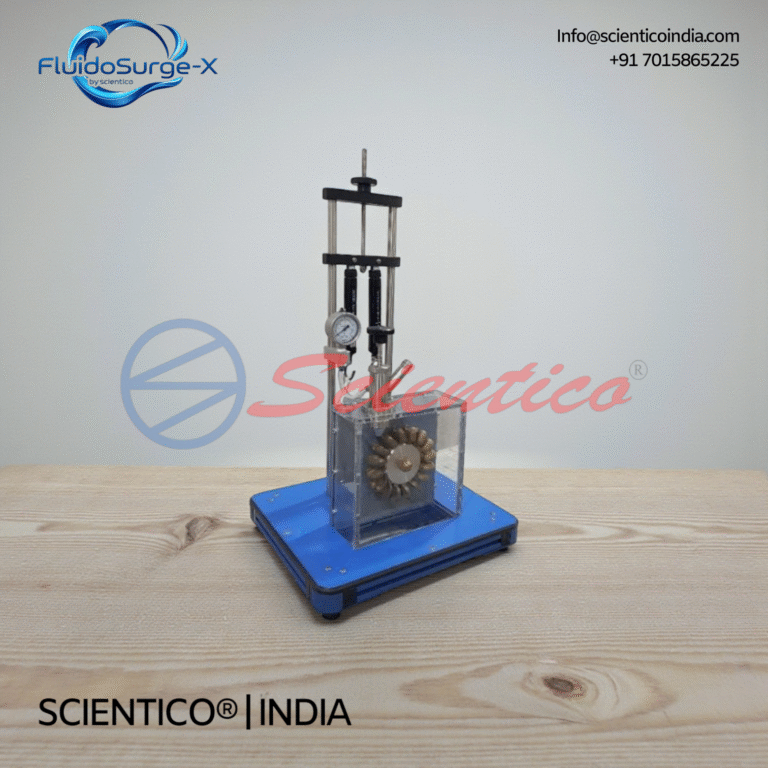
Pelton Turbine Apparatus | FluidoSurge-X 156
The Pelton Turbine Apparatus FluidoSurge-X 156 is designed to demonstrate the operating principles and performance characteristics of an impulse turbine. It enables experimental study of jet impact, torque generation, speed variation, and efficiency under controlled conditions. The apparatus operates with a hydraulic bench or laboratory water supply in a closed water circuit. It is suitable for fluid mechanics and hydraulic machinery laboratory instruction.
View product detailsHow does a Pelton wheel turbine work?
Water under high head is delivered through a penstock to a nozzle. The nozzle accelerates the water into a free jet of velocity V. A spear (needle) valve inside the nozzle controls the jet area a, and therefore the discharge, without losing efficiency. The jet hits the splitter ridge at the centre of each bucket, which divides the flow into two halves. Each half is turned through a large angle and discharged sideways, so the bucket extracts nearly all of the jet’s momentum. The wheel rotates at peripheral (tangential) speed u, and a series of buckets passes continuously in front of the jet so that the full jet is always doing work.
What is the working principle and governing equation?
The Pelton wheel works on the impulse-momentum principle: force equals the rate of change of momentum of the jet. For a series of buckets (the practical case), every bucket interception means the full jet is intercepted, so the mass-flow rate is based on the full jet:
Mass-flow term = ρ · a · V
Here ρ is water density, a is jet cross-sectional area and V is jet velocity. The water enters a bucket with relative velocity (V − u) and leaves deflected through a large angle. The force on the runner in the direction of motion is:
F = ρ · a · V · (V − u) · (1 + k · cos φ)
and the power developed is:
P = F · u
where:
- V = absolute jet velocity
- u = peripheral (tangential) speed of the wheel
- a = cross-sectional area of the jet
- k = friction factor for flow over the bucket surface (k < 1, accounting for friction loss)
- φ = bucket outlet tip angle, the supplement of the deflection angle
In a real bucket the water cannot be turned a full 180° because the outgoing stream would strike the back of the following bucket. So the bucket tip angle φ is kept small, typically about 10°–20°, which means the jet is actually deflected through roughly 160°–170°. Because φ is small, cos φ is close to +1, so the term (1 + k·cosφ) is near its maximum and the force on the runner is high.
At what speed is a Pelton wheel most efficient?
Differentiating the power equation with respect to u shows that, ideally, maximum power occurs when the wheel speed is half the jet speed (u = V/2). In practice, allowing for friction and mechanical losses, peak efficiency is reached at a slightly lower ratio, with the speed ratio u ≈ 0.46–0.48 V. This is why Pelton runners are designed so the bucket pitch-line speed sits in this band at the rated head.
| Symbol / Quantity | Meaning | Typical value |
|---|---|---|
| V | Jet velocity | Set by head and nozzle |
| u | Wheel peripheral speed | ≈ 0.46–0.48 V |
| φ | Bucket outlet tip angle | ≈ 10°–20° |
| Deflection | Total turning of jet | ≈ 160°–170° |
| k | Bucket friction factor | < 1 |
What are the main parts of a Pelton wheel turbine?
- Nozzle and spear (needle) valve: Convert pressure head to a high-velocity jet and regulate the jet area to match the load.
- Runner (wheel): A disc carrying the buckets on its rim; it converts jet momentum into rotation.
- Buckets (vanes): Double, ellipsoidal, spoon-shaped cups with a central splitter ridge that divides the jet and turns each half through a large angle.
- Casing: Encloses the runner, prevents splashing and directs spent water to the tailrace; it carries no pressure since the wheel runs at atmospheric pressure.
- Braking jet: A small auxiliary nozzle that sprays the back of the buckets to slow the wheel quickly when shutting down.
- Shaft and bearings: Transmit the developed torque to the generator or dynamometer.
Uses and applications of the Pelton wheel turbine
- High-head hydroelectric plants: The preferred turbine for heads from roughly 150 m up to over 1,000 m, typical of mountain and reservoir-fed schemes.
- Micro- and mini-hydro: Compact Pelton units power remote villages, farms and resorts from streams with a strong vertical drop.
- Engineering and fluid-mechanics laboratories: Bench-scale Pelton test rigs let students measure head, discharge, speed, torque and brake power, then plot efficiency and characteristic curves and verify the u ≈ V/2 result experimentally.
- Pump-as-turbine and energy-recovery duty: Used to recover energy from high-pressure water flows in industrial and water-supply systems.
In a teaching laboratory, a Pelton wheel apparatus turns this theory into measured data, helping students connect the impulse-momentum equation to real efficiency curves. Scientico India, an ISO 9001:2015 and model-specific manufacturer and exporter of engineering and science teaching equipment, supplies Pelton wheel test rigs and complete hydraulics benches for engineering colleges and universities in India and worldwide. Explore the full range on our Fluid Mechanics Lab Equipment page.
Frequently Asked Questions
Why is a Pelton wheel called an impulse turbine?
Because energy is transferred to the runner purely through the change in momentum (impulse) of a free water jet. The water strikes the buckets at atmospheric pressure, with no pressure drop across the runner, unlike reaction turbines such as Francis or Kaplan.
What is the ideal speed ratio for a Pelton wheel?
Ideally the wheel peripheral speed should be half the jet velocity (u = V/2). In practice, accounting for friction and mechanical losses, peak efficiency occurs at a speed ratio of about u = 0.46 to 0.48 V.
Why is the bucket not turned through a full 180 degrees?
If the jet were deflected a full 180 degrees, the outgoing water would strike the back of the next bucket and reduce efficiency. So the bucket outlet tip angle is kept at about 10 to 20 degrees, giving an actual deflection of roughly 160 to 170 degrees while keeping cos of the tip angle near +1 for high force.
Where are Pelton wheel turbines used?
They are used in high-head hydroelectric plants (heads from about 150 m to over 1,000 m), in micro and mini-hydro installations, in engineering and fluid-mechanics teaching laboratories, and for energy recovery from high-pressure water flows.
What does the spear valve do in a Pelton turbine?
The spear or needle valve moves inside the nozzle to vary the jet area, and therefore the discharge, so the turbine output can be matched to the load without significant loss of efficiency.
Engineering labs demonstrate these principles on a Pelton wheel turbine test rig, plotting efficiency against speed and load.
One honest ask
We don't gate anything on this site. You just read the whole thing free. If it was useful, leave your email and two things happen: we send you this page as a plain-text block you can paste into a tender file or an internal email, and we notify you the next time we publish a buyer tool like this one. Nothing else. No drip sequence, no sales calls booked without asking.