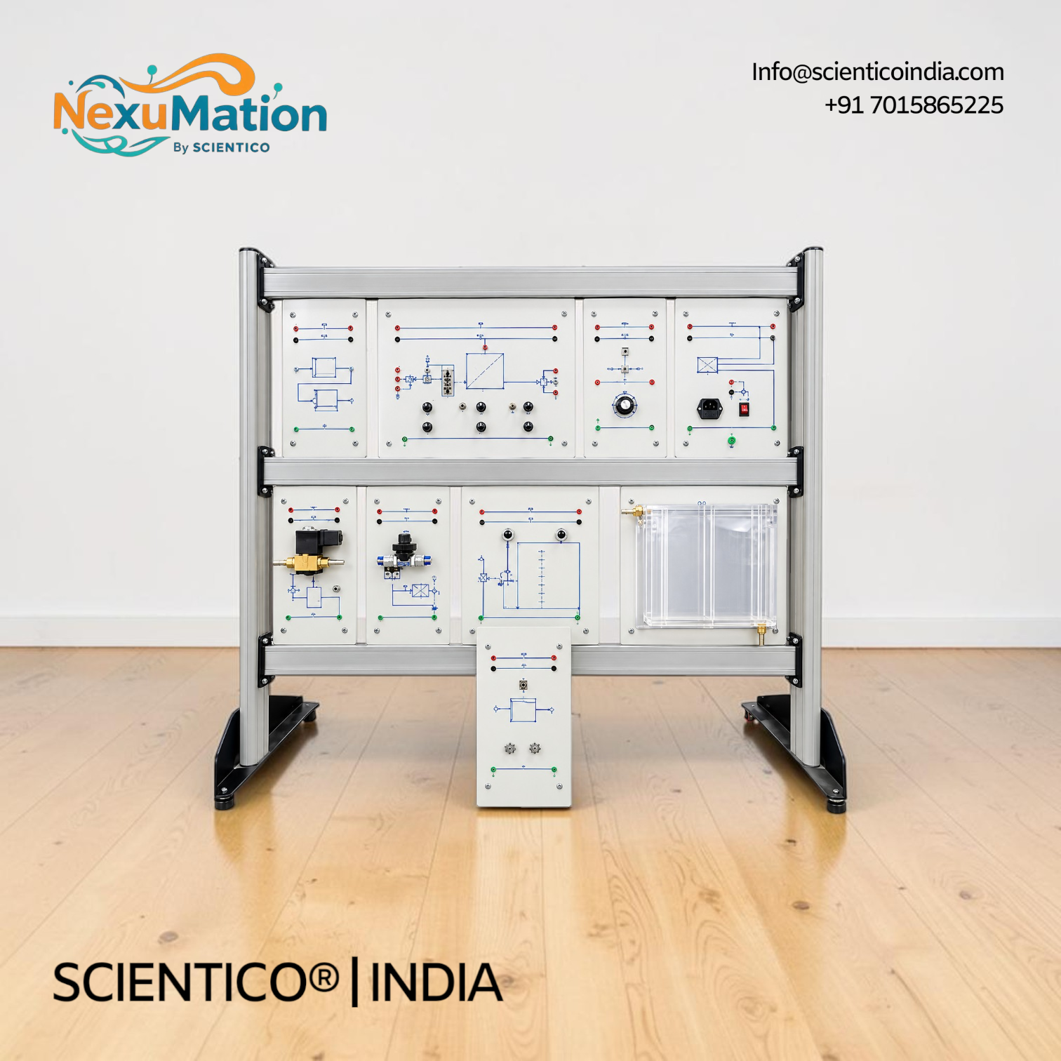
Flow Control Training System (Modular Type) | NexuMation 63
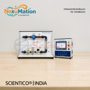
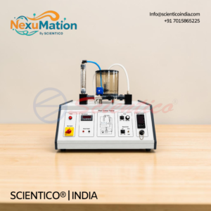
The Flow Control Training System (Modular Type) NexuMation 63 is a modular trainer on a vertical three-level frame. This flow control training system includes a receptacle with pump, filling tank, turbine flow meter (10 … 100 l/h), solenoid valve, and 30 W power amplifier. PID ranges are Kp = 0 … 1000, TI = 1ms … 100s, and TD = 0.2ms … 20s. A USB DAQ system and management software are included.
The Flow Control Training System (Modular Type) NexuMation 63 is designed for the study of flow control application. This flow control training system gives students practical training through guided experiments. Industrial type components are educationally adapted using a modular panel system.
Product Overview
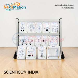
The Flow Control Training System (Modular Type) NexuMation 63 has a modular structure. Educational panels are installed on a vertical frame. A theoretical and practical manual is supplied.
The modular panel system permits step-by-step assembling. Students build from the simplest circuit to the most complex system. This gives a direct and immediate approach to flow control topics.
The flow control training system includes a turbine flow meter, a solenoid valve, a receptacle with pump, and a filling tank. It also includes a computerized DAQ system via USB and management software.
Flow Control Training System (Modular Type) NexuMation 63: Technical Specifications
| Parameter | Value |
|---|---|
| Structure | Modular, educational panels on vertical frame |
| Work Frame | Three-level |
| Controllers | PID controller, proportional controller |
| Flow Measurement | Turbine flow meter, 10 … 100 l/h |
| Flow Process | Receptacle with pump, filling tank, solenoid valve |
| Data Acquisition | Computerized DAQ system via USB |
| Software | Management software |
| Documentation | Theoretical and practical manual |
Technical Data
| Module | Specification |
|---|---|
| DC Power Supply | Output voltages: +15 V; 0 V; -15 V. Output current: 2.4 A (3 A for a short period). Single-phase mains supply. Short-circuit protected. Two LEDs (+15 V; -15 V) for nominal voltage indication. Mains switch with pilot lamp |
| Voltage Reference Generator | Power supply: +15 V; 0 V; -15 V. Continuous regulation reference signal: -10 V to +10 V, 0 to +10 V. Step reference signal: -10 V to +10 V, 0 to +10 V. Switch: internal potentiometer or external reference signal. Switch: 0 / ±10 V range or 0 / +10 V range |
| PID Controller | Power supply: +15 V; 0 V; -15 V. Signal voltage range: -10V … +10V. Kp = 0 … 1000. TI = 1ms … 100s. TD = 0.2ms … 20s. Input summing node: references UR and UC, controlled variable UA. Parameters continuously adjustable, coarse and fine adjustment of Kp, TI, TD. Reset input of integral controller, input Ioff for resetting I controller. Output summing node for noise variables. Error signal measurement terminal. Output offset adjustment screw. Three LED indicators of sense of deviation. Over-range LED “over” above 10 V or below -10 V |
| Proportional Controller | Power supply: +15 V; 0 V; -15 V. Signal voltage range: -10V … +10V. Kp = 0 … 100. Three position switch coarse setting, potentiometer fine setting. LED indicator of over-range |
| Power Amplifier | Power supply: +15 V; 0 V; -15 V. Signal voltage range: -10V … +10V. Output voltage: -10 V … +10 V to ground; 0 … ±20 V symmetrically. Max. output power: 30 W, short-circuit protected |
| Receptacle With Pump | Vessel capacity: 1.5 l approx. Signal voltage range: 0 … +10 V. Pump power consumption: 10 W max. |
| Filling Tank | Tank capacity: approx. 1 l |
| Turbine Flow Meter | Power supply: ± 15 V. Measurement range: 10 … 100 l/h. Measurement temperature: 20°C. Measurement medium: water |
| Solenoid Valve | Power supply: + 15V. Control voltage: > 1 |
| True RMS Meter | Automatic scaling. Voltage: 0 .. 1000V DC; 0 .. 1000VACpp; 0 .. 750VACRMS. Current: 0 .. 20 A DC; 0 .. 28 A ACpp; 0 .. 20A ACRMS. Accuracy: +/-0.5%. Resolution: 16bits. Refresh rate: 0.5s. Power supply: 90-260 Vac 50/60Hz. Power consumption: 3 VA. Communication: Modbus (RS485) |
| Single Pole Switch | Plug-in element, normally open. Switch load: 2 A, 250V |
Key Features
- Structure: modular panels on vertical frame
- Application: flow control training system for guided experiments
- Work Frame: three-level
- Controllers: PID and proportional
- PID Parameters: Kp = 0 … 1000, TI = 1ms … 100s, TD = 0.2ms … 20s
- Power Supply: +15 V; 0 V; -15 V, 2.4 A
- Power Amplifier: 30 W max., short-circuit protected
- Flow Sensing: turbine flow meter, 10 … 100 l/h
- Meter: True RMS, Modbus (RS485), 16bits
- Data Acquisition: computerized DAQ system via USB
- Software: management software included
Experiments
- Measurement system’s features
- Analysis of flow control features
Construction and Design
The Flow Control Training System (Modular Type) NexuMation 63 is built on a vertical frame. Educational panels are installed in a modular arrangement. A three-level work frame organizes the components.
Industrial type components are educationally adapted. The modular panel system permits step-by-step assembly. Students progress from the simplest circuit to the most complex system.
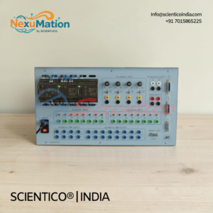
The flow control training system includes a receptacle with pump and a filling tank. A turbine flow meter measures flow. A solenoid valve is fitted in the circuit. Controller, power amplifier, and switch modules plug into the frame. A connecting leads set is supplied for interconnection.
A computerized DAQ system connects via USB. Management software runs the experiments.
Software
- Computerized DAQ system via USB
- Management software
Scope of Delivery
- DC Power Supply
- Voltage Reference Generator
- PID Controller
- Proportional Controller
- Power Amplifier
- Receptacle With Pump
- Filling Tank
- Turbine Flow Meter
- Solenoid Valve
- True RMS Meter
- Single Pole Switch
- Computerized DAQ system via USB
- Management software
- Connecting Leads Set
- Three-level work frame
- Theoretical and practical manual
Q1. What is the Flow Control Training System (Modular Type) NexuMation 63 designed for?
It is designed for the study of flow control application through guided experiments.
Q2. Which controllers are included in this flow control training system?
A PID controller and a proportional controller.
Q3. What are the PID controller ranges?
Kp = 0 … 1000, TI = 1ms … 100s, and TD = 0.2ms … 20s.
Q4. How is the flow measured?
A turbine flow meter measures flow in the range of 10 … 100 l/h. The measurement medium is water.
Q5. How does the flow control training system connect to a computer?
A computerized DAQ system via USB is included, with management software.
Need Assistance? We're Here to Help!
Connect with our team for product specifications, pricing, and customized solutions for your institution or project.