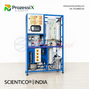
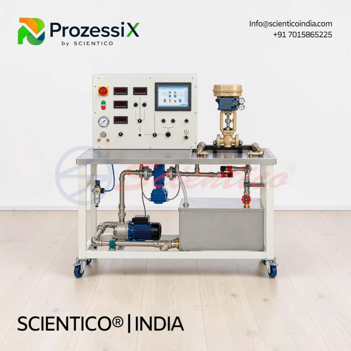
Test Stand for Control Valves | Prozessi PX-32
The Test Stand for Control Valves Prozessi PX-32 characterizes control valves using a 90 L water circuit and two-stage pump. This control valve test stand determines Kv and Kvs values, plots valve characteristics, and analyses step response, with electromagnetic flow measurement and USB data acquisition.
The Test Stand for Control Valves Prozessi PX-32 is a water-circuit trainer for testing and characterizing control valves. This control valve test stand determines Kv and Kvs values and plots valve characteristics using step-response analysis.
Product Overview
The PX-32 control valve test stand uses a 90 L water tank and a two-stage centrifugal pump with 22 m maximum head and 5.4 m³/h maximum flow. A gate valve sets flow, which an electromagnetic sensor measures from 0 to 4500 L/h. Two 0 to 6 bar pressure sensors measure pressure upstream and downstream of the valve. Electro-pneumatic valves are actuated by potentiometer with 4 to 20 mA signal and supplied air at 0 to 6 bar. Motorised valves are operated by pushbuttons. Position feedback uses current or resistance signals. USB data acquisition runs on Windows.
Test Stand for Control Valves Prozessi PX-32 — Technical Specifications
| Parameter | Value |
|---|---|
| Application | Testing and characterization of control valves |
| Water Tank Capacity | Approximately 90 L |
| Pump Type | Two-stage centrifugal |
| Maximum Pump Head | 22 m |
| Maximum Pump Flow Rate | 5.4 m³/h |
| Flow Rate Adjustment | Gate valve |
| Flow Measurement | Electromagnetic flow sensor |
| Flow Measurement Range | 0 to 4500 L/h |
| Water Pressure Sensors | 2, 0 to 6 bar |
| Air Pressure Measurement Range | 0 to 6 bar |
| Electro-Pneumatic Actuation | Potentiometer with 4 to 20 mA DC signal |
| Motorised Valve Actuation | Pushbuttons |
| Electro-Pneumatic Pressure Adjustment | Pressure regulator and manometer |
| Resistance Feedback Signal | 0 to 1000 Ω |
| Auxiliary Power Supply | 24 V AC |
| Position Feedback, Electro-Pneumatic | Current signal |
| Position Feedback, Motorised | Resistance teletransmitter |
| Data Acquisition | USB interface, Windows software |
| Power Supply | 230 V, 50/60 Hz, single-phase |
Technical Data
Water Circuit:
- Tank capacity: approximately 90 L
- Two-stage centrifugal pump, 22 m maximum head, 5.4 m³/h maximum flow
- Gate valve for flow adjustment
- Electromagnetic flow sensor, 0 to 4500 L/h
Pressure Measurement:
- Two water pressure sensors, 0 to 6 bar
- Air pressure measurement, 0 to 6 bar
Valve Actuation and Feedback:
- Electro-pneumatic valves: potentiometer with 4 to 20 mA DC signal
- Motorised valves: pushbuttons
- Electro-pneumatic pressure: regulator and manometer
- Feedback: current signal (electro-pneumatic), resistance teletransmitter (motorised), 0 to 1000 Ω
Electrical:
- Auxiliary supply: 24 V AC
- Power: 230 V, 50/60 Hz, single-phase
Key Features
- Kv and Kvs Determination: Measures valve flow coefficients
- Valve Characterization: Plots characteristics and step-response curves
- Electromagnetic Flow Measurement: 0 to 4500 L/h range
- Differential Pressure Monitoring: Upstream and downstream pressure across the valve
- Dual Actuation: Potentiometer control for electro-pneumatic valves and pushbuttons for motorised valves
- Supply Pressure Study: Adjustable air pressure from 0 to 6 bar
- Position Feedback: Current and resistance signals
- USB Data Acquisition: Windows-compatible software
Experiments
- Determination of Kv and Kvs values
- Plotting of control valve characteristics
- Analysis of dynamic valve response using step-response curves
- Measurement of pressure drop across a control valve
- Investigation of flow rate and valve operating behaviour
- Study of supply pressure effects on electro-pneumatic valves
- Valve maintenance, adjustment, and calibration practice
Construction and Design
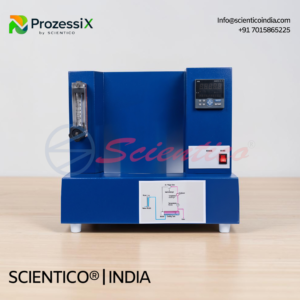
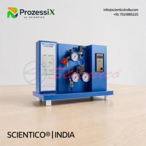
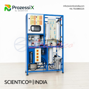
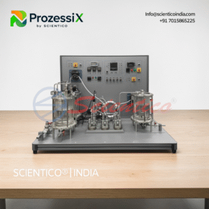
The PX-32 stand comprises a water tank, a two-stage centrifugal pump, and a water circuit with connections for the valve under test. A gate valve adjusts flow, and an electromagnetic sensor measures it. Two pressure sensors sit upstream and downstream of the valve. A pressure regulator and manometer set the air supply for electro-pneumatic valves.
Software
USB-based data acquisition software compatible with Windows. The Windows version and detailed software functions are not specified in the supplied information.
Scope of Delivery
- Control valve test stand
- Water tank (approximately 90 L)
- Two-stage centrifugal pump
- Water circuit and valve connections
- Electromagnetic flow sensor
- Two water pressure sensors
- Gate valve
- Potentiometer for electro-pneumatic valve actuation
- Pushbuttons for motorised valve actuation
- Manometer and pressure regulator
- Valve position feedback arrangements
- USB data acquisition software
Q: What does the Test Stand for Control Valves Prozessi PX-32 determine?
A: It determines Kv and Kvs values and plots control valve characteristics.
Q: How is flow measured on the PX-32?
A: An electromagnetic flow sensor measures flow from 0 to 4500 L/h, with a gate valve for adjustment.
Q: How are the valves actuated?
A: Electro-pneumatic valves are actuated by potentiometer with a 4 to 20 mA DC signal. Motorised valves use pushbuttons.
Q: What software is supplied with the PX-32?
A: USB data acquisition software compatible with Windows. The specific Windows version is not specified.
Need Assistance? We're Here to Help!
Connect with our team for product specifications, pricing, and customized solutions for your institution or project.