
Multi Point Electronic Injection System Panel Board
Model Torquemaster-54
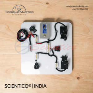
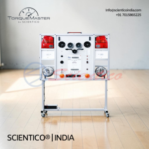
Multi Point Electronic Injection System Panel Board Torquemaster-54 is an automotive training panel for electronic fuel injection.
It demonstrates multi-point sequential injection with an IAW-59F electronic control unit.
The panel includes six engine sensors, electronic injectors, fuel pump control, and idle air control.
Testing terminals, LED and digital displays, and sensor and actuator fault simulation support hands-on study.
It has a heavy-duty metal frame with locking wheels and overload and short-circuit protection.
The Multi Point Electronic Injection System Panel Board is an automotive training panel for demonstrating and studying electronic fuel injection. It covers a multi-point fuel injection (MPFI) system with an IAW-59F electronic control unit.
Product Overview
The Multi Point Electronic Injection System Panel Board is a training panel for demonstration and study of electronic fuel injection. It covers multi-point sequential electronic fuel injection with an IAW-59F electronic control unit. The panel includes an engine coolant temperature sensor, an intake air temperature sensor, a manifold absolute pressure (MAP) sensor, a throttle position sensor (TPS), a crankshaft position sensor, and an oxygen sensor. It also includes electronic fuel injectors, a fuel pump control system, and an idle air control (IAC) system. The panel is built on a heavy-duty metal frame with locking wheels.
Multi Point Electronic Injection System Panel Board Torquemaster-54: Technical Specifications
| Parameter | Value |
|---|---|
| System | Multi-point fuel injection (MPFI) |
| Training Function | Demonstration and study of electronic fuel injection |
| Fuel Injection | Multi-point sequential electronic fuel injection demonstration |
| Sensor System | Engine coolant temperature sensor, intake air temperature sensor, MAP sensor, TPS, crankshaft position sensor, oxygen sensor |
| Actuator System | Electronic fuel injectors, fuel pump control system, idle air control (IAC) system |
| Display | LED indicator and digital display for system operation |
| Testing Points | Electrical testing terminals for sensors and actuators |
| Fault Simulation | Sensor and actuator fault simulation |
| Wiring Diagram | Complete electrical wiring diagram |
| Construction | Heavy-duty metal frame with mounted training components |
| Mobility | Wheels with locking mechanism |
| Safety | Overload and short-circuit protection |
| Application | Automotive engineering training and demonstration |
Technical Data
- Electronic Control
- Multi-point sequential electronic fuel injection
- Sensors
- Engine coolant temperature sensor
- Intake air temperature sensor
- Manifold absolute pressure (MAP) sensor
- Throttle position sensor (TPS)
- Crankshaft position sensor
- Oxygen sensor
- Actuators
- Electronic fuel injectors
- Fuel pump control system
- Idle air control (IAC) system
- Display and Testing
- LED indicator and digital display
- Electrical testing terminals for sensors and actuators
- Fault Simulation
- Sensor and actuator fault simulation
- Construction and Safety
- Heavy-duty metal frame
- Wheels with locking mechanism
- Overload and short-circuit protection
Key Features
- MPFI System: multi-point sequential electronic fuel injection
- Sensor Set: six engine sensors including MAP, TPS, and oxygen sensor
- Actuators: electronic injectors, fuel pump control, idle air control
- Diagnostics: electrical testing terminals and LED/digital display
- Fault Simulation: sensor and actuator faults
- Mobility: heavy-duty frame with locking wheels
Experiments
- Identify the sensors and actuators of the MPFI system
- Measure sensor signals at the electrical testing terminals
- Observe sequential operation of the electronic fuel injectors
- Observe fuel pump control and its operation
- Observe idle air control (IAC) operation
- Monitor system operation on the LED indicator and digital display
- Simulate sensor faults and observe the system response
- Simulate actuator faults and observe the system response
- Trace circuits using the complete electrical wiring diagram
Construction and Design
The panel uses a heavy-duty metal frame with the training components mounted on it. The frame is fitted with wheels and a locking mechanism. The wiring is laid out according to the complete electrical wiring diagram.
Scope of Delivery
- All necessary connecting wires, cables, and accessories
- User manual
- Technical training manual
What fuel injection system does the panel demonstrate?
It demonstrates multi-point sequential electronic fuel injection (MPFI).
Can faults be simulated?
Yes. Sensor and actuator faults can be simulated for study.
How are sensors and actuators tested?
Electrical testing terminals are provided for each sensor and actuator.
Is the panel mobile?
Yes. It has wheels with a locking mechanism.
Need Assistance? We're Here to Help!
Connect with our team for product specifications, pricing, and customized solutions for your institution or project.