Lighting Training Board Simulator | Torquemaster-28
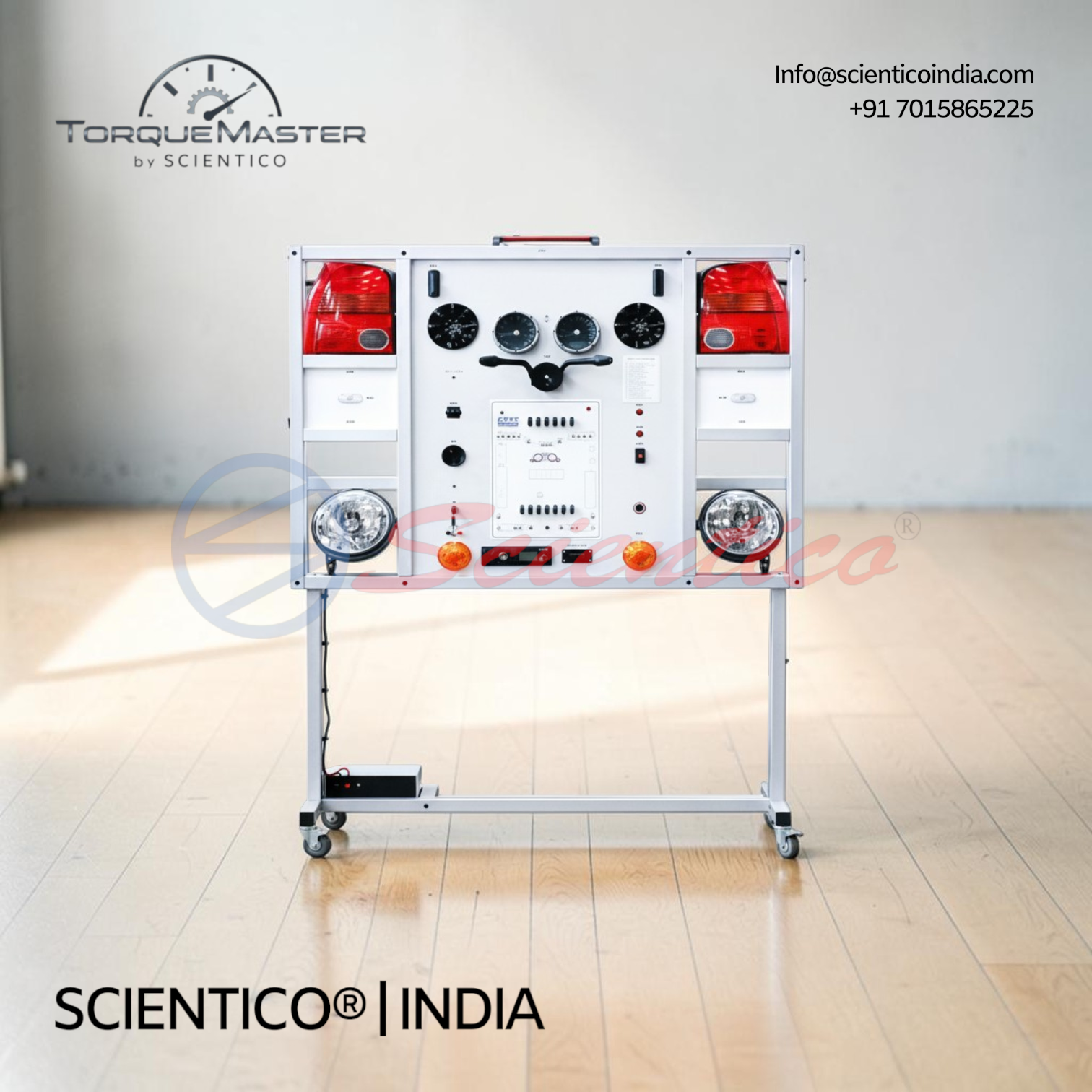
Lighting Training Board Simulator Torquemaster-28 teaches automotive lighting system structure and diagnostics through a fully functional training system on a mobile aluminum frame. This Lighting Training Board Simulator includes OBD 16-pin diagnostic connector for fault code reading/erasing, live data display, adjustable headlight beam motors, 12V battery, 220/12V power supply, automotive oscilloscope, and built-in wiring diagram with banana plug jumpers for electrical measurements and component testing.
The Lighting Training Board Simulator Torquemaster-28 is a great educational tool that allows students to learn the structure of a lighting system, study its components, and perform various measurements, tests, and diagnostic procedures. This Lighting Training Board Simulator demonstrates the structure and components of automotive lighting systems.
Product Overview
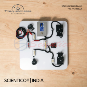
The Torquemaster-28 can be used as a visual aid for students of mechanical subjects to demonstrate and explain the structure and components of lighting systems. This automotive training stand also serves as educational equipment for lighting system repair and service procedures. The Lighting Training Board Simulator is a fully functional lighting training system installed in a mobile aluminum frame. An electric wiring diagram with built-in banana plug jumpers allows for measurements and connecting or disconnecting components. The apparatus provides the ability to measure electrical signal parameters of system components and perform control unit diagnosis through an OBD 16-pin diagnostic connector. Students can read and erase fault codes, display operating system parameters through live data, and activate actuators depending on the control unit capabilities.
Lighting Training Board Simulator Torquemaster-28 — Technical Specifications
| Parameter | Value |
|---|---|
| Model | Torquemaster-28 |
| System Type | Fully functional lighting training system in mobile aluminum frame |
| Wiring Diagram | Built-in banana plug jumpers for measurements and connections |
| Headlight Adjustment | Adjustable beam levels with front headlight motors |
| Diagnostic Interface | OBD 16-pin diagnostic connector |
| Control Unit | Electronic control unit (ECU) identification |
| Power Supply | 12V battery and 220/12V power supply unit |
| Measurement Tool | Automotive oscilloscope |
| Features | Fault code reading/erasing, live data display, actuator activation |
| Length x Width x Height (approx.) | 1800 x 1400 x 500 mm |
| Weight (approx.) | 80 kg |
Technical Data
Lighting System Components
| Component | Detail |
|---|---|
| Headlights | Adjustable beam levels with motors |
| Wiring System | Electric wiring diagram with banana plug jumpers |
| Battery | 12V battery |
| Power Supply | 220/12V power supply unit |
Diagnostic and Measurement
| Component | Detail |
|---|---|
| Diagnostic Connector | OBD 16-pin diagnostic connector |
| Control Unit | Electronic control unit (ECU) for identification |
| Electrical Measurement | Ability to measure electrical signal parameters |
| Oscilloscope | Automotive oscilloscope for waveform analysis |
| Fault Code Management | Reading and erasing fault codes |
| Live Data | Operating system parameters display |
| Actuator Control | Activation depending on control unit capabilities |
Key Features
- Measurement Capability: Ability to measure electrical signal parameters of system components
- Diagnostic Functions: Control unit diagnosis through OBD 16-pin diagnostic connector
- Fault Management: Reading and erasing fault codes
- Live Data Display: Operating system parameters visible for monitoring
- Actuator Control: Activation of actuators depending on control unit capabilities
- Adjustability: Adjustable beam levels with front headlight motors
- Wiring Diagram: Built-in banana plug jumpers for measurements and component connection/disconnection
- Design Type: Lighting Training Board Simulator for comprehensive lighting system training
Experiments
- Study of automotive lighting system structure and components
- Measurement of electrical signal parameters at various test points
- Electronic control unit (ECU) identification and function
- Fault code reading and interpretation
- Fault code erasing procedures
- Live data observation of operating system parameters
- Headlight beam level adjustment and measurement
- Actuator activation and response observation
- Lighting circuit continuity and resistance measurements
- Waveform analysis using automotive oscilloscope
- Lighting system diagnostic troubleshooting procedures
Construction and Design
The Lighting Training Board Simulator Torquemaster-28 is a fully functional lighting training system installed in a mobile aluminum frame. An electric wiring diagram is integrated with built-in banana plug jumpers, allowing for accurate measurements and easy connection or disconnection of system components. Front headlights are fitted with adjustable beam level motors for demonstration and adjustment training. An electronic control unit (ECU) is included for identification and diagnostic purposes. The system is powered by a 12V battery and includes a 220/12V power supply unit for flexible operation. An automotive oscilloscope is provided for waveform analysis and electrical signal measurement. The OBD 16-pin diagnostic connector enables control unit diagnosis, fault code reading and erasing, live data parameter display, and actuator activation functions.
Scope of Delivery
- Lighting training board simulator in mobile aluminum frame
- Front headlights with adjustable beam level motors
- Electric wiring diagram with banana plug jumpers
- Electronic control unit (ECU)
- 12V battery
- 220/12V power supply unit
- OBD 16-pin diagnostic connector
- Automotive oscilloscope
Required for Operation
- 220V AC power supply for the 220/12V power supply unit
Optional Accessories
- Headlight tester for adjustable beam level training
Q1: What does the Lighting Training Board Simulator Torquemaster-28 teach?
A: It teaches the structure of automotive lighting systems, component identification, electrical measurements, diagnostics, and fault code procedures.
Q2: Can fault codes be read and erased with this simulator?
A: Yes, the OBD 16-pin diagnostic connector allows reading and erasing of fault codes from the control unit.
Q3: What diagnostic capabilities does this simulator have?
A: It can perform control unit diagnosis, display live operating system parameters, measure electrical signal parameters, and activate actuators depending on the control unit.
Q4: Can headlight beam levels be adjusted on this trainer?
A: Yes, front headlights have adjustable beam levels with motors for demonstration and adjustment training.
Q5: What are the dimensions and weight of the simulator?
A: The approximate dimensions are 1800 x 1400 x 500 mm, with an approximate weight of 80 kg.
Need Assistance? We're Here to Help!
Connect with our team for product specifications, pricing, and customized solutions for your institution or project.