Power Door Lock System Trainer | Torquemaster-35
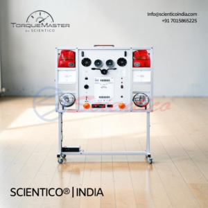
Power Door Lock System Trainer Torquemaster-35 demonstrates automotive power door lock system operation using OEM components mounted on a plastic training board. This Power Door Lock System Trainer includes 2 door lock actuators, door lock relay, lockable fault box with 4 insertable faults, electrical test points, and a set of 21 colour-coded jumper leads for circuit assembly. Students can follow OEM wiring diagrams to build circuits and perform diagnostic troubleshooting. Requires external 12V DC power.
The Power Door Lock System Trainer Torquemaster-35 is a functional trainer mounted on a plastic training board designed to demonstrate power door lock system operation. This Power Door Lock System Trainer allows students to learn the structure and components of automotive door locking systems.
Product Overview
The Torquemaster-35 can be used as a visual aid for students of mechanical subjects to demonstrate and explain the structure and components of power door lock systems. This automotive training stand also serves as educational equipment for door lock system repair and service procedures. Power door locks, also known as electric door locks or central locking, allow the driver or front passenger to simultaneously lock or unlock all the doors of an automobile or truck by pressing a button or flipping a switch. The remote locking system confirms successful locking and unlocking through either a light or a horn signal, and usually offers an option to switch easily between these two variants. Light signals are more discreet while horn signals might create a nuisance in residential neighborhoods and other busy parking areas. The Power Door Lock System Trainer features OEM components including door lock actuators and switches with OEM matching wire colours. A lockable system fault box allows instructors to insert from one to four faults for student diagnostic learning. Electrical test points are included for circuit diagnosis, and students can wire the circuit using supplied leads and included OEM wiring diagrams.
Power Door Lock System Trainer Torquemaster-35 — Technical Specifications
| Parameter | Value |
|---|---|
| Model | Torquemaster-35 |
| Mounting | Plastic training board |
| Door Lock Actuators | 2 units, OEM components |
| Door Lock Relay | Included |
| Fault Box | Lockable fault box with 4 faults |
| Test Points | Electrical test points for circuit diagnosis |
| Jumper Leads | Set of 21 jumper leads, 24 inch (60 cm): 6 red, 1 black, 14 blue |
| Wiring Diagrams | OEM wiring diagrams included |
| Components | OEM components with OEM matching wire colours |
| Power Supply Required | External 12V DC |
| Length x Width x Height (approx.) | 550 x 400 x 300 mm |
| Weight (approx.) | 20 kg |
Technical Data
| Component | Detail |
|---|---|
| Door Lock Actuators | 2 units, OEM components |
| Control System | Door lock relay for actuator control |
| Fault Insertion | Lockable fault box, allows 1 to 4 fault insertions |
| Test Terminal Block | Receptacles for diagnostic test points |
| Wiring Configuration | OEM wiring diagrams with supplied jumper leads |
| Jumper Lead Set | 21 leads total: 6 red, 1 black, 14 blue, each 24 inch (60 cm) |
| Confirmation System | Light or horn signal for lock/unlock confirmation |
Key Features
- Components: OEM components (door lock actuators, switches, with OEM matching wire colours)
- Fault Box: Lockable system fault box allowing 1 to 4 fault insertions for diagnostic learning
- Diagnostic Points: Electrical test points included on the trainer for circuit diagnosis
- Wiring System: Students can wire the circuit using supplied leads and included OEM wiring diagrams
- Jumper Leads: Set of 21 jumper leads, 24 inch (60 cm) with colour coding (6 red, 1 black, 14 blue)
- Confirmation Signals: Light or horn signal capability for lock/unlock confirmation
- Design Type: Power Door Lock System Trainer for comprehensive door lock system training and diagnostics
Experiments
- Study of power door lock actuator operation
- Study of door lock relay function and control
- Study of central locking system wiring and circuits
- Measurement of electrical signals at test points
- Fault insertion and diagnostic troubleshooting
- Lock and unlock signal response observation
- Light and horn confirmation signal demonstration
- Circuit continuity and resistance measurements
- Wiring diagram interpretation and circuit assembly
- Door lock control switch function study
Construction and Design
The Power Door Lock System Trainer Torquemaster-35 is mounted on a plastic training board for stable and accessible operation. It features OEM components throughout, including two door lock actuators and a door lock relay with OEM matching wire colours. A lockable system fault box with capacity for one to four faults is integrated for diagnostic training. Electrical test points are provided for circuit measurement and analysis. A set of 21 colour-coded jumper leads, each 24 inch (60 cm) long, is supplied to allow students to assemble the circuit according to the included OEM wiring diagrams. The system can confirm successful locking and unlocking through either light or horn signals. The trainer requires an external 12V DC power supply for operation and includes a user manual.
Scope of Delivery
- Power door lock system trainer on plastic training board
- 2 door lock actuators, OEM components
- Door lock relay
- Lockable fault box with 4 faults
- Electrical test point terminal blocks
- Set of 21 colour-coded jumper leads (24 inch/60 cm each)
- OEM wiring diagrams
- User manual
Required for Operation
- External 12V DC power supply
Q1: What does the Power Door Lock System Trainer Torquemaster-35 demonstrate?
A: It demonstrates the structure and operation of a power door lock system, including the actuators, relay, control circuits, and confirmation signals used in modern automobiles.
Q2: How many door lock actuators are included?
A: Two door lock actuators are included to demonstrate the power door lock system operation.
Q3: How many faults can be inserted using the fault box?
A: The lockable system fault box allows instructors to insert from one to four faults for student diagnostic learning.
Q4: Can students assemble the circuit themselves?
A: Yes, students can wire the circuit using the supplied jumper leads and included OEM wiring diagrams.
Q5: What are the dimensions and weight of the trainer?
A: The approximate dimensions are 550 x 400 x 300 mm, with an approximate weight of 20 kg.
Need Assistance? We're Here to Help!
Connect with our team for product specifications, pricing, and customized solutions for your institution or project.