
The flywheel experiment is a classic Theory of Machines and Engineering Mechanics practical used to determine the mass moment of inertia of a rotating flywheel. The moment of inertia is a fundamental property governing the rotational dynamics of all rotating machinery, engines, turbines, compressors, and punching machines all rely on flywheels to store rotational kinetic energy and smooth out speed fluctuations.
Equipment mentioned in this guide
Review the product information, specifications and model before requesting a quotation.
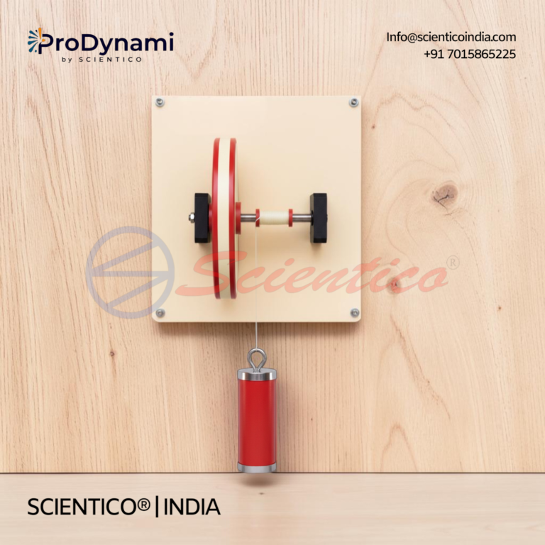
Flywheel Apparatus | ProDynami – 1201
The Flywheel Apparatus ProDynami - 1201 demonstrates the working principle of a flywheel and its practical significance in industry. This Fly Wheel Apparatus shows how a flywheel stores rotational energy when supply exceeds requirement, and delivers energy when requirement exceeds supply.
View product details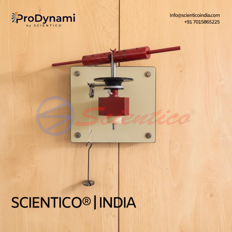
Inertia In Rotational Motion Apparatus | ProDynami – 1204
The Inertia In Rotational Motion Apparatus ProDynami - 1204 enables experiments on rotational motion in general. This Inertia In Rotational Motion Apparatus allows weights to be fitted to a rotating rod at marked distances from the centre, forming a dumbbell-shaped arrangement. Its inertia properties can be changed easily and recalculated.
View product detailsAim of the Experiment
To determine the mass moment of inertia (I) of a flywheel about its axis of rotation using the falling-mass method, and to compare it with the theoretical value calculated from its dimensions.
Theory
Moment of Inertia
The mass moment of inertia (I) is the rotational analogue of mass. It quantifies a body’s resistance to angular acceleration about an axis. For a flywheel, it depends on the mass distribution relative to the axis of rotation.
For a solid disc flywheel: I = (1/2)MR squared, where M = mass, R = radius.
Falling-Mass Method Principle
A known mass m is attached to a cord wound around the flywheel axle of radius r. When released, the mass falls through a height h, unwinding the cord and accelerating the flywheel. By the principle of conservation of energy:
Potential energy lost by falling mass = Kinetic energy of mass + Kinetic energy of flywheel + Energy lost to friction
mgh = (1/2)mv squared + (1/2)I omega squared + n1 x Wf
where v = velocity of mass when cord leaves axle, omega = angular velocity of flywheel = v/r, n1 = number of revolutions during the fall, Wf = work done against friction per revolution.
Working Formula
After the mass detaches, the flywheel continues rotating and comes to rest after n2 revolutions due to friction. The friction work per revolution is found from the second phase. Combining both phases gives the moment of inertia:
I = [m(2gh – v squared) / omega squared] x [n2 / (n1 + n2)]
where omega = 2(pi)N/60 and N is the maximum rpm reached at the instant the mass detaches.
Apparatus Required
- Flywheel apparatus (heavy cast-iron flywheel mounted on a horizontal axle in bearings)
- Set of known masses with hanger
- Cord (inextensible, thin, strong)
- Stopwatch
- Steel rule and Vernier caliper (for measuring axle radius and flywheel dimensions)
- Tachometer (optional, for direct rpm measurement)
- Revolution counter or chalk mark for counting revolutions
Procedure
- Measure the diameter of the axle with a Vernier caliper and calculate the radius r. Measure the flywheel diameter and mass for theoretical calculation.
- Wind the cord evenly around the axle and attach the known mass m to the free end. Note the number of turns of cord wound (this determines the height of fall h = number of turns x circumference of axle).
- Mark a reference point on the flywheel rim with chalk for counting revolutions.
- Release the mass and simultaneously start the stopwatch. Count the number of revolutions n1 made by the flywheel until the cord completely unwinds and the mass detaches.
- Record the time t1 for the mass to fall the height h.
- After the mass detaches, count the number of revolutions n2 the flywheel makes before coming to rest, and the time t2.
- Repeat the experiment 3 times with the same mass and 2 times with different masses for accuracy.
Observation Table
| Trial | Mass m (kg) | Height h (m) | n1 (rev during fall) | t1 (s) | n2 (rev to stop) | N max (rpm) | I (kg m squared) |
|---|---|---|---|---|---|---|---|
| 1 | |||||||
| 2 | |||||||
| 3 |
Calculations
Maximum angular velocity: omega = 2(pi)N/60 (rad/s)
Velocity of mass at detachment: v = omega x r (m/s)
Moment of inertia: I = [m(2gh – v squared) / omega squared] x [n2 / (n1 + n2)] (kg m squared)
Theoretical (solid disc): I_th = (1/2)MR squared
Percentage error = (I_exp – I_th)/I_th x 100 percent
Applications of Flywheels
- IC engines: Smooth out the power pulses from individual cylinder firing strokes
- Punching and shearing machines: Store energy during idle period, release it during the punch stroke
- Rolling mills and presses: Provide high torque during the working stroke
- Energy storage systems: Flywheel energy storage (FES) for grid stabilisation and regenerative braking
Difference Between Flywheel and Governor
| Flywheel | Governor |
|---|---|
| Controls speed fluctuation within a single cycle | Controls mean speed over varying load |
| Stores and releases energy | Regulates fuel/energy supply |
| No effect on fuel supply | Directly controls fuel supply |
| Continuous action | Acts only when load changes |
Viva Questions
- Define moment of inertia. What are its units?
- What is the difference between a flywheel and a governor?
- What is the radius of gyration? How is it related to moment of inertia?
- Why is the flywheel made heavy at the rim rather than near the centre?
- State the parallel axis theorem.
- What is the coefficient of fluctuation of energy?
- Give three engineering applications of flywheels.
Scientico India manufactures this and the full range of Theory of Machines equipment, model-specific and supplied to engineering colleges worldwide.
Related simple-machine experiments: Screw Jack, Worm & Worm Wheel, and Single & Double Purchase Winch Crab.
One honest ask
We don't gate anything on this site. You just read the whole thing free. If it was useful, leave your email and two things happen: we send you this page as a plain-text block you can paste into a tender file or an internal email, and we notify you the next time we publish a buyer tool like this one. Nothing else. No drip sequence, no sales calls booked without asking.