
Equipment mentioned in this guide
Review the product information, specifications and model before requesting a quotation.
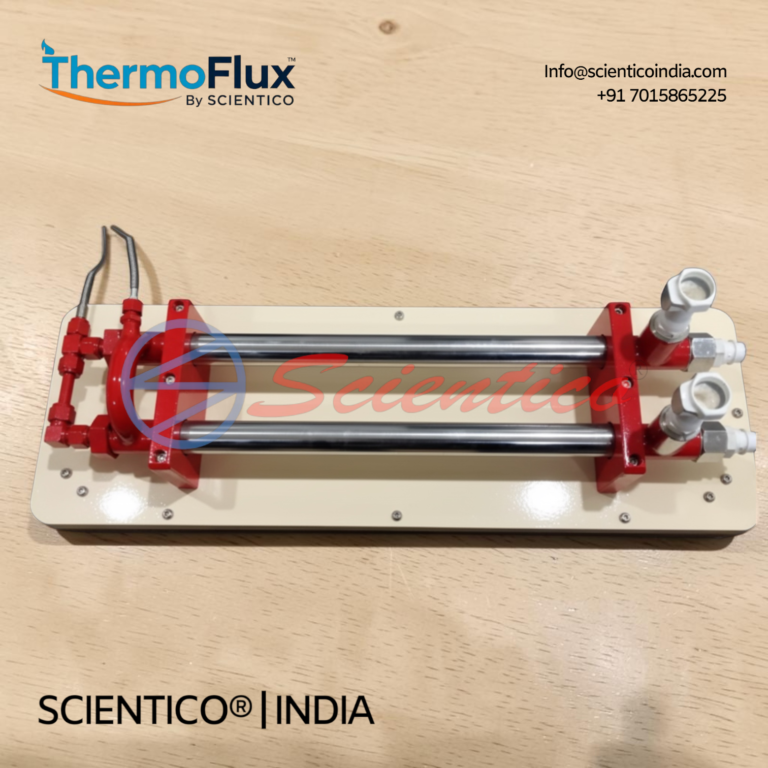
Concentric Tube Heat Exchanger | ThermoFlux – 7108/2
The Concentric Tube Heat Exchanger ThermoFlux - 7108/2 is a laboratory unit designed to study heat transfer through a concentric tube configuration under parallel flow and counter flow conditions. This concentric tube heat exchanger consists of two copper concentric tubes with hot water circulating through the internal tube and cold water circulating through the annular space, with K-type thermocouple sensors at multiple measurement points including inlet, outlet, and midpoint locations for both fluid streams.
View product detailsAim of the Experiment
To determine the overall heat transfer coefficient and to compare the performance of a double pipe heat exchanger in parallel flow and counter flow configurations using the LMTD method.
Apparatus Required
- Double pipe heat exchanger apparatus (concentric tube heat exchanger)
- Hot water heater/generator with temperature control
- Rotameters for hot and cold water flow measurement
- Temperature sensors (PT100 or thermocouples) at 4 points
- Control valves for parallel/counter flow switching
Theory
A double pipe (concentric tube) heat exchanger consists of two concentric pipes. Hot fluid flows through the inner pipe and cold fluid through the annular space (or vice versa). This is the simplest type of heat exchanger.
Heat balance: Q = ṁ_h × Cp_h × (T_h1 − T_h2) = ṁ_c × Cp_c × (T_c2 − T_c1)
Overall heat transfer coefficient: U = Q / (A × LMTD)
For parallel flow: LMTD = [(T_h1 − T_c1) − (T_h2 − T_c2)] / ln[(T_h1 − T_c1)/(T_h2 − T_c2)]
For counter flow: LMTD = [(T_h1 − T_c2) − (T_h2 − T_c1)] / ln[(T_h1 − T_c2)/(T_h2 − T_c1)]
Procedure
- Set up the apparatus in parallel flow mode (both fluids entering at the same end).
- Start the heater and set the hot water temperature to 60°C.
- Adjust cold water flow rate to the required value using the rotameter.
- Wait for steady-state conditions (approximately 15–20 minutes).
- Record T_h1, T_h2 (hot fluid inlet and outlet) and T_c1, T_c2 (cold fluid inlet and outlet).
- Record hot water and cold water flow rates (ṁ_h and ṁ_c).
- Calculate Q, LMTD, and U for parallel flow.
- Switch to counter flow configuration by changing the valve settings.
- Repeat steps 4–7 for counter flow and compare results.
Observation Table
| Sr. No. | T_h1 (°C) | T_h2 (°C) | T_c1 (°C) | T_c2 (°C) | ṁ_h (kg/s) | ṁ_c (kg/s) | Q (W) | LMTD (°C) | U (W/m²K) |
|---|---|---|---|---|---|---|---|---|---|
| 1 (Parallel) | |||||||||
| 2 (Counter) |
Result
Overall heat transfer coefficient U (parallel flow) = _______ W/m²K. Overall heat transfer coefficient U (counter flow) = _______ W/m²K. Counter flow gives a higher LMTD and therefore a higher U for the same flow conditions.
Internal Links
Related: Heat Transfer Lab Equipment | Shell and Tube Heat Exchanger Experiment | Heat Conduction Experiment | Convection Experiment
Get Heat Transfer Lab Equipment
Scientico India manufactures ISO 9001:2015 and model-specific heat transfer lab apparatus. Contact us for specifications and CIF pricing.
Scientico India manufactures this and the full range of Heat Transfer & Thermodynamics equipment, model-specific and supplied to engineering colleges worldwide.
Explore Heat Transfer & Thermodynamics Equipment → or request a quoteDouble Pipe Heat Exchanger, LMTD Calculation and Overall HTC
LMTD for Parallel Flow (Co-current)
In parallel flow, both hot and cold fluids enter the exchanger from the same end:
ΔT₁ = T_hi – T_ci (temperature difference at inlet)
ΔT₂ = T_ho – T_co (temperature difference at outlet)
LMTD_parallel = (ΔT₁ – ΔT₂) / ln(ΔT₁/ΔT₂)
LMTD for Counter Flow (Counter-current)
In counter flow, hot fluid enters from one end and cold fluid from the other:
ΔT₁ = T_hi – T_co (hot inlet vs cold outlet)
ΔT₂ = T_ho – T_ci (hot outlet vs cold inlet)
LMTD_counter = (ΔT₁ – ΔT₂) / ln(ΔT₁/ΔT₂)
Key finding: Counter flow always gives higher LMTD than parallel flow for the same terminal temperatures → higher heat transfer rate for the same area → more thermally efficient.
Overall Heat Transfer Coefficient U
Heat duty: Q = m_h × c_ph × (T_hi – T_ho) = m_c × c_pc × (T_co – T_ci)
Q = U × A × LMTD
Therefore: U = Q / (A × LMTD)
Theoretical U from individual film coefficients: 1/U = 1/h_i + r_i × ln(r_o/r_i)/k + r_i/r_o × 1/h_o
(for thin-walled tubes where r_i ≈ r_o): 1/U ≈ 1/h_i + 1/h_o
Observation Table
| Mode | T_hi (°C) | T_ho (°C) | T_ci (°C) | T_co (°C) | Q (W) | LMTD (°C) | U (W/m²K) |
|---|---|---|---|---|---|---|---|
| Parallel flow | |||||||
| Counter flow |
Effectiveness-NTU Method
Effectiveness ε = actual heat transfer / maximum possible heat transfer
ε = Q_actual / (C_min × (T_hi – T_ci))
where C_min = min(m_h×c_ph, m_c×c_pc) = minimum heat capacity rate
NTU = U × A / C_min
For counter flow: ε = [1 – exp(-NTU(1-C_r))] / [1 – C_r×exp(-NTU(1-C_r))]
where C_r = C_min/C_max
One honest ask
We don't gate anything on this site. You just read the whole thing free. If it was useful, leave your email and two things happen: we send you this page as a plain-text block you can paste into a tender file or an internal email, and we notify you the next time we publish a buyer tool like this one. Nothing else. No drip sequence, no sales calls booked without asking.