Gas Turbine Jet Engine | ThermoFlux – 7086
The Gas Turbine Jet Engine ThermoFlux – 7086 is a fully functioning aero-derivative turbojet engine test stand with a thrust range of 10 to 100 N, maximum speed of 120,000 rpm, and kerosene fuel consumption of 550 ml/min at maximum thrust. The single-shaft engine features a centrifugal compressor, multi-injector combustion chamber, and ceramic-bearing centrifugal turbine mounted on sliding rails with a linear thrust transducer on a wheeled trolley. This gas turbine jet engine unit measures temperature across five points (3x 0 to 1200°C and 2x -100 to 400°C), pressure (1x -1 to 1 bar and 4x 0 to 4 bar), differential pressure (-25 to 25 kPa), speed (0 to 120,000 rpm), and force (0 to 200 N), with all data shown on a physical mimic panel and DAQ screen display. Optional LabVIEW-based DAQ software is available for Windows-based PC data acquisition.
The Gas Turbine Jet Engine ThermoFlux – 7086 is a fully functioning, instrumented aero-derivative small turbojet engine test stand designed to enable students to study jet engine performance, energy balance, specific thrust, and specific fuel consumption across a thrust range of 10 to 100 N. This gas turbine jet engine unit features a single-shaft engine with centrifugal compressor, multi-injector combustion chamber, centrifugal turbine with ceramic bearings, electronic thrust measurement, and a full suite of temperature, pressure, speed, and force sensors displayed on a physical mimic panel and data acquisition system.
Product Overview
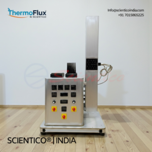
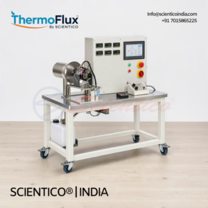
The Gas Turbine Jet Engine ThermoFlux – 7086 is mounted on a wheeled trolley for mobility. The engine assembly and air inlet unit are mounted on two sliding rails constrained by a linear thrust transducer for direct thrust measurement. The engine is a single-shaft design incorporating a single-stage centrifugal compressor, a combustion chamber fed by multiple fuel injectors, and a single-stage centrifugal turbine. A tailpipe ducts exhaust gas into a thrust-producing jet. Ceramic bearings in the turbine eliminate the need for lubricating oil. A protective grating is fitted over the jet engine.
Air is ducted into the engine via a calibrated nozzle for determination of air mass volume. Fuel is kerosene with a lubricant mix, pumped by a small electrically driven gear pump controlled precisely by the Engine Control Unit to directly regulate engine speed. Operator control is via a throttle lever. Starting is provided by a decoupling electric starter for fully automatic start-up. Maximum speed is 120,000 rpm with an idle speed of 32,000 rpm. Fuel consumption at maximum thrust is 550 ml/min. Full power pressure is slightly over 2 bar.
Temperature measurements are taken at five points: air inlet, fuel inlet, compressor outlet, combustion chamber outlet, and tailpipe stream. Pressure measurements cover ambient air pressure, air inlet differential pressure, and compressor outlet pressure. Thrust range is 10 to 100 N, measured electronically by a force sensor (0 to 200 N range). Speed is measured up to 120,000 rpm.
Measuring ranges cover differential pressure (-25 to 25 kPa), pressure (1x -1 to 1 bar, 4x 0 to 4 bar), temperature (3x 0 to 1200°C and 2x -100 to 400°C), speed (0 to 120,000 rpm), and force (0 to 200 N). A physical mimic diagram displays temperatures of the gas flow and engine pressure ratio. A data acquisition system records and displays all indications on screen. Optional LabVIEW-based DAQ software is available for PC-based data acquisition.
Gas Turbine Jet Engine ThermoFlux – 7086, Technical Specifications
| Parameter | Value |
|---|---|
| Engine Type | Single-shaft, aero-derivative turbojet |
| Compressor Type | Single-stage centrifugal |
| Turbine Type | Single-stage centrifugal |
| Turbine Bearings | Ceramic (oil-free) |
| Combustion Chamber | Multiple fuel injectors |
| Thrust Range | 10 to 100 N |
| Thrust Measurement | Electronic, linear thrust transducer |
| Engine Weight | 1430 g |
| Overall Engine Size | 265 mm x 111 mm |
| Ancillaries Weight (incl. battery) | 410 g |
| Maximum RPM | 120,000 rpm |
| Idle RPM | 32,000 rpm |
| Idle Thrust | 0.45 kg / 1 lb |
| Full Power Pressure | Slightly over 2 bar |
| Fuel Type | Kerosene with lubricant mix |
| Fuel Delivery | Electrically driven gear pump, Engine Control Unit controlled |
| Fuel Consumption at Max Thrust | 550 ml/min |
| Operator Control | Throttle lever |
| Starting System | Decoupling electric starter, fully automatic |
| Mounting | Two sliding rails on wheeled trolley |
| Differential Pressure Range | -25 to 25 kPa |
| Pressure Range | 1x -1 to 1 bar / 4x 0 to 4 bar |
| Temperature Range (High) | 3x 0 to 1200°C |
| Temperature Range (Standard) | 2x -100 to 400°C |
| Speed Measuring Range | 0 to 120,000 rpm |
| Force Measuring Range | 0 to 200 N |
| Exhaust | Low back pressure duct or direct external vent |
Technical Data
Jet Engine
| Parameter | Value |
|---|---|
| Thrust | 100 N / 10 kg |
| Engine Weight | 1430 g |
| Overall Size | 265 mm x 111 mm (10.4″ x 4.4″) |
| Ancillaries Weight (incl. battery) | 410 g |
| Maximum RPM | 120,000 rpm |
| Idle RPM | 32,000 rpm |
| Idle Thrust | 0.45 kg / 1 lb |
Fuel
| Parameter | Value |
|---|---|
| Fuel Type | Kerosene with jet oil lubricant mix |
| Fuel Consumption at Max Thrust | 550 ml/min |
Thrust
| Parameter | Value |
|---|---|
| Thrust Range | 10 to 100 N |
| Measurement Method | Electronic |
Speed and Pressure
| Parameter | Value |
|---|---|
| Maximum Speed | 120,000 rpm |
| Full Power Pressure | Slightly over 2 bar |
Exhaust
| Parameter | Value |
|---|---|
| Exhaust Duct | Very low back pressure |
| Venting Option | Direct vent to outside area |
Measuring Ranges
| Parameter | Value |
|---|---|
| Differential Pressure | -25 to 25 kPa |
| Pressure | 1x -1 to 1 bar / 4x 0 to 4 bar |
| Temperature (High Range) | 3x 0 to 1200°C |
| Temperature (Standard Range) | 2x -100 to 400°C |
| Speed | 0 to 120,000 rpm |
| Force | 0 to 200 N |
Key Features
- Gas Turbine Jet Engine Type: Single-shaft aero-derivative turbojet, single-stage centrifugal compressor and turbine
- Thrust Range: 10 to 100 N, measured electronically via linear thrust transducer
- Force Measurement Range: 0 to 200 N
- Maximum Speed: 120,000 rpm, idle 32,000 rpm
- Turbine Bearings: Ceramic, oil-free operation
- Combustion Chamber: Multiple fuel injectors
- Fuel: Kerosene with lubricant mix, gear pump controlled by Engine Control Unit
- Fuel Consumption at Max Thrust: 550 ml/min
- Operator Control: Throttle lever
- Starting System: Decoupling electric starter, fully automatic
- Engine Dimensions: 265 mm x 111 mm, weight 1430 g
- Mounting: Two sliding rails on wheeled trolley
- Temperature Measurement: 3x 0 to 1200°C and 2x -100 to 400°C across five measurement points
- Pressure Measurement: 1x -1 to 1 bar and 4x 0 to 4 bar
- Differential Pressure Range: -25 to 25 kPa
- Speed Measurement Range: 0 to 120,000 rpm
- Display: Physical mimic diagram for gas flow temperatures and engine pressure ratio
- Data Acquisition: DAQ system records and displays all data on screen
- Exhaust: Low back pressure duct or direct external vent
- Protective Grating: Fitted over jet engine
- Software: Optional LabVIEW-based DAQ software, Windows compatible
Experiments
- Demonstration of the turbojet principle
- Performance analysis of a turbojet at varying power
- Behaviour during operation of a jet engine including start-up procedure
- Determination of specific thrust
- Determination of specific fuel consumption
- Determination of lambda (fuel-air ratio)
Construction and Design
The Gas Turbine Jet Engine ThermoFlux – 7086 is assembled on a wheeled trolley for ease of positioning and storage. The complete engine and air inlet assembly is mounted on two sliding rails constrained by a linear thrust transducer, enabling direct electronic thrust measurement from 0 to 200 N. The engine is a single-shaft design with a single-stage centrifugal compressor, a multi-injector combustion chamber, and a single-stage centrifugal turbine. Ceramic bearings in the turbine eliminate the requirement for lubricating oil. A tailpipe ducts exhaust gas to a thrust-producing jet, with a low back pressure exhaust duct or direct external vent available.
Air enters via a calibrated nozzle for air mass volume determination. Fuel is kerosene with a lubricant mix, delivered by an electrically driven gear pump controlled by the Engine Control Unit for direct speed regulation. Operator input is via a throttle lever. Starting is fully automatic using a decoupling electric starter. A protective grating covers the engine.
Five temperature measurement points cover air inlet, fuel inlet, compressor outlet, combustion chamber outlet, and tailpipe, with ranges of 3x 0 to 1200°C and 2x -100 to 400°C. Pressure is measured at ambient, air inlet differential (-25 to 25 kPa), and compressor outlet, across ranges of 1x -1 to 1 bar and 4x 0 to 4 bar. Speed is measured from 0 to 120,000 rpm. This gas turbine jet engine unit displays all readings on a physical mimic diagram and a DAQ-based screen display system.
Software
ThermoFlux – 7086 Software (Optional)
- Developed in the National Instruments LabVIEW environment
- Designed specifically for data acquisition with this apparatus
- Records and displays all engine performance data on screen
- A set of electronic sensors is included when the software option is selected
- Compatible with any Windows operating system
Scope of Delivery
- 1 experimental unit
- 1 instructional manual
Q1: What type of engine is used in the Gas Turbine Jet Engine ThermoFlux – 7086?
The unit uses a single-shaft aero-derivative turbojet engine with a single-stage centrifugal compressor, a combustion chamber with multiple fuel injectors, and a single-stage centrifugal turbine with ceramic bearings. The ceramic bearings eliminate the need for lubricating oil.
Q2: What is the thrust range and how is it measured in this gas turbine jet engine unit?
The thrust range is 10 to 100 N and is measured electronically using a linear thrust transducer constraining the engine and air inlet assembly on sliding rails. The force sensor measuring range covers 0 to 200 N.
Q3: What fuel does the engine use and how is it controlled?
The engine uses kerosene with a lubricant mix. Fuel is delivered by a small electrically driven gear pump controlled precisely by the Engine Control Unit, which directly regulates engine speed. The operator uses a throttle lever for speed control.
Q4: What temperatures and pressures are measured and at which locations?
Temperatures are measured at five points: air inlet, fuel inlet, compressor outlet, combustion chamber outlet, and tailpipe stream. Ranges are 3x 0 to 1200°C and 2x -100 to 400°C. Pressure measurements cover ambient air, air inlet differential pressure (-25 to 25 kPa), and compressor outlet, across ranges of 1x -1 to 1 bar and 4x 0 to 4 bar.
Q5: How are the measurement results displayed on this gas turbine jet engine test stand?
Results are displayed on a physical mimic diagram that shows gas flow temperatures and engine pressure ratio. A DAQ-based system also records and displays all indications on a screen. Optional LabVIEW-based DAQ software is available for full PC-based data acquisition on any Windows operating system.
Need Assistance? We're Here to Help!
Connect with our team for product specifications, pricing, and customized solutions for your institution or project.