🔎 Manufacturer-direct laboratory equipment enquiries - Request a model-specific international quotation →
✓ Established 1993 ✓ Model-Specific Specifications ✓ Manufacturer-Direct Enquiries ✓ International Quotations ✓ Destination-Based Delivery Terms

Test Stand for Control Valves

Model Prozessi PX-32

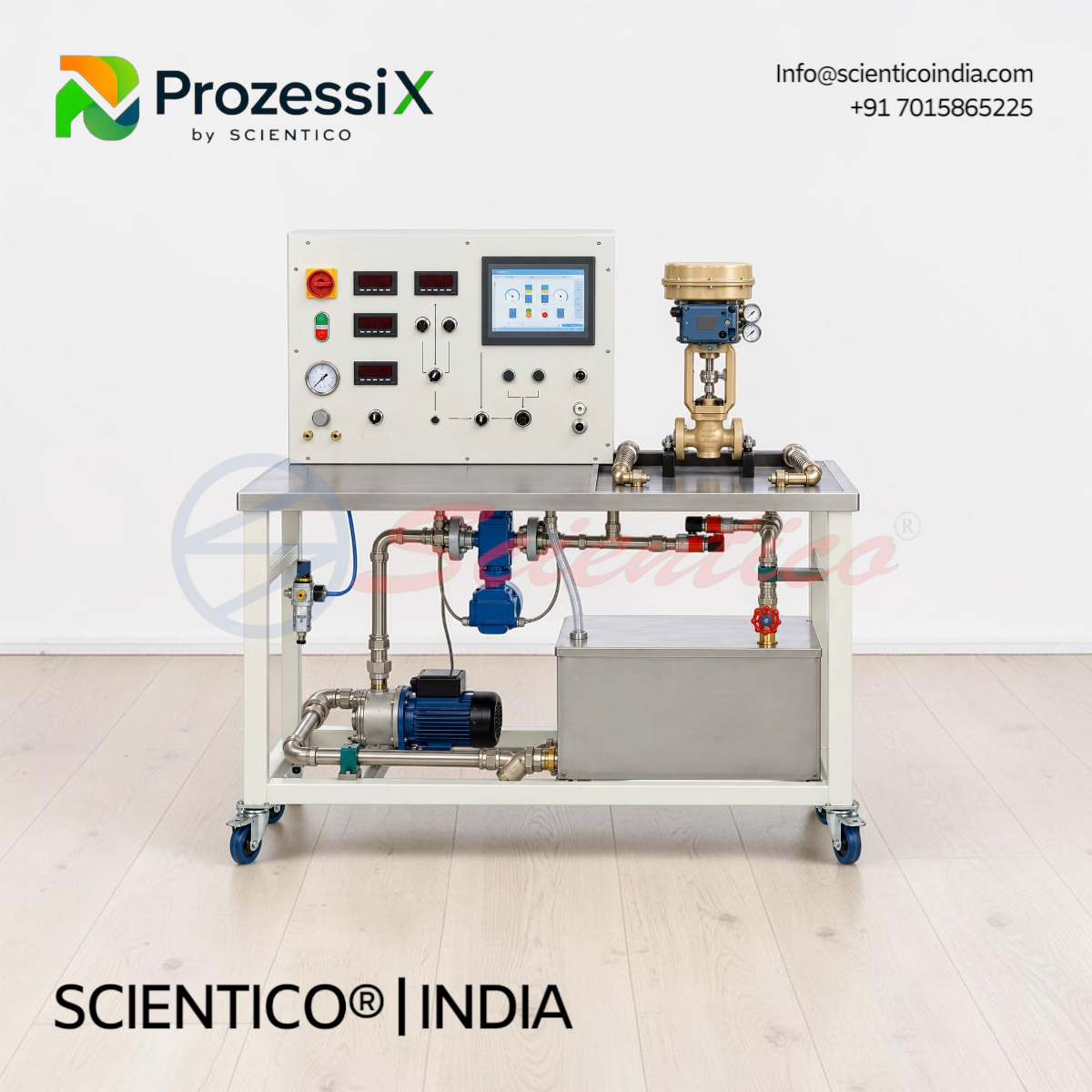
The Test Stand for Control Valves Prozessi PX-32 characterizes control valves using a 90 L water circuit and two-stage pump. This control valve test stand determines Kv and Kvs values, plots valve characteristics, and analyses step response, with electromagnetic flow measurement and USB data acquisition.

The Test Stand for Control Valves Prozessi PX-32 is a water-circuit trainer for testing and characterizing control valves. This control valve test stand determines Kv and Kvs values and plots valve characteristics using step-response analysis.

Product Overview

The PX-32 control valve test stand uses a 90 L water tank and a two-stage centrifugal pump with 22 m maximum head and 5.4 m³/h maximum flow. A gate valve sets flow, which an electromagnetic sensor measures from 0 to 4500 L/h. Two 0 to 6 bar pressure sensors measure pressure upstream and downstream of the valve. Electro-pneumatic valves are actuated by potentiometer with 4 to 20 mA signal and supplied air at 0 to 6 bar. Motorised valves are operated by pushbuttons. Position feedback uses current or resistance signals. USB data acquisition runs on Windows.

Test Stand for Control Valves Prozessi PX-32 — Technical Specifications

Parameter Value
Application Testing and characterization of control valves
Water Tank Capacity Approximately 90 L
Pump Type Two-stage centrifugal
Maximum Pump Head 22 m
Maximum Pump Flow Rate 5.4 m³/h
Flow Rate Adjustment Gate valve
Flow Measurement Electromagnetic flow sensor
Flow Measurement Range 0 to 4500 L/h
Water Pressure Sensors 2, 0 to 6 bar
Air Pressure Measurement Range 0 to 6 bar
Electro-Pneumatic Actuation Potentiometer with 4 to 20 mA DC signal
Motorised Valve Actuation Pushbuttons
Electro-Pneumatic Pressure Adjustment Pressure regulator and manometer
Resistance Feedback Signal 0 to 1000 Ω
Auxiliary Power Supply 24 V AC
Position Feedback, Electro-Pneumatic Current signal
Position Feedback, Motorised Resistance teletransmitter
Data Acquisition USB interface, Windows software
Power Supply 230 V, 50/60 Hz, single-phase

Technical Data

Water Circuit:

  • Tank capacity: approximately 90 L
  • Two-stage centrifugal pump, 22 m maximum head, 5.4 m³/h maximum flow
  • Gate valve for flow adjustment
  • Electromagnetic flow sensor, 0 to 4500 L/h

Pressure Measurement:

  • Two water pressure sensors, 0 to 6 bar
  • Air pressure measurement, 0 to 6 bar

Valve Actuation and Feedback:

  • Electro-pneumatic valves: potentiometer with 4 to 20 mA DC signal
  • Motorised valves: pushbuttons
  • Electro-pneumatic pressure: regulator and manometer
  • Feedback: current signal (electro-pneumatic), resistance teletransmitter (motorised), 0 to 1000 Ω

Electrical:

  • Auxiliary supply: 24 V AC
  • Power: 230 V, 50/60 Hz, single-phase

Key Features

  • Kv and Kvs Determination: Measures valve flow coefficients
  • Valve Characterization: Plots characteristics and step-response curves
  • Electromagnetic Flow Measurement: 0 to 4500 L/h range
  • Differential Pressure Monitoring: Upstream and downstream pressure across the valve
  • Dual Actuation: Potentiometer control for electro-pneumatic valves and pushbuttons for motorised valves
  • Supply Pressure Study: Adjustable air pressure from 0 to 6 bar
  • Position Feedback: Current and resistance signals
  • USB Data Acquisition: Windows-compatible software

Experiments

  • Determination of Kv and Kvs values
  • Plotting of control valve characteristics
  • Analysis of dynamic valve response using step-response curves
  • Measurement of pressure drop across a control valve
  • Investigation of flow rate and valve operating behaviour
  • Study of supply pressure effects on electro-pneumatic valves
  • Valve maintenance, adjustment, and calibration practice

Construction and Design

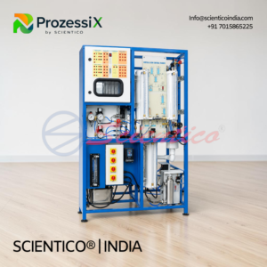
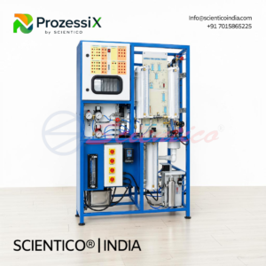
The PX-32 stand comprises a water tank, a two-stage centrifugal pump, and a water circuit with connections for the valve under test. A gate valve adjusts flow, and an electromagnetic sensor measures it. Two pressure sensors sit upstream and downstream of the valve. A pressure regulator and manometer set the air supply for electro-pneumatic valves.

Software

USB-based data acquisition software compatible with Windows. The Windows version and detailed software functions are not specified in the supplied information.

Scope of Delivery

  • Control valve test stand
  • Water tank (approximately 90 L)
  • Two-stage centrifugal pump
  • Water circuit and valve connections
  • Electromagnetic flow sensor
  • Two water pressure sensors
  • Gate valve
  • Potentiometer for electro-pneumatic valve actuation
  • Pushbuttons for motorised valve actuation
  • Manometer and pressure regulator
  • Valve position feedback arrangements
  • USB data acquisition software

Q: What does the Test Stand for Control Valves Prozessi PX-32 determine?
A: It determines Kv and Kvs values and plots control valve characteristics.

Q: How is flow measured on the PX-32?
A: An electromagnetic flow sensor measures flow from 0 to 4500 L/h, with a gate valve for adjustment.

Q: How are the valves actuated?
A: Electro-pneumatic valves are actuated by potentiometer with a 4 to 20 mA DC signal. Motorised valves use pushbuttons.

Q: What software is supplied with the PX-32?
A: USB data acquisition software compatible with Windows. The specific Windows version is not specified.

Need Assistance? We're Here to Help!

Connect with our team for product specifications, pricing, and customized solutions for your institution or project.

Trade enquiries

Distributors, dealers, resellers and bulk buyers

We manufacture Test Stand for Control Valves | Prozessi PX-32 at our own works in Ambala, India. Manufacturer-direct, three ways to work with us.

01

Become a distributor, dealer or agent in your territory

Already selling to colleges or hospitals in your market? Add a manufacturer-direct line. Terms reviewed on application.

or message on WhatsApp
02

Wholesale and bulk quotation

Holding a live enquiry? Send the model, quantity, destination and required Incoterm. We will confirm the supplied scope and available export documents.

or message on WhatsApp
03

OEM authorisation letter for a tender

Bidding a tender that requests a manufacturer authorisation form (MAF)? Send the tender reference, deadline and listed equipment so we can confirm what can be issued.

or message on WhatsApp

Full distributor guide OEM and export enquiries

Process Engineering TechnologyModel Prozessi PX-32
🏭
Manufacturer DirectProduct-specific enquiry, not a generic catalogue
🌍
Destination MatchedConfiguration and delivery scope reviewed together
📄
Decision-Ready ReplyApplicable documentation confirmed before ordering
Product-specific enquiry

Get a quotation your team can evaluate

A bare price can hide configuration, accessories, voltage, documentation and delivery assumptions. Send the product and destination now so the quoted scope can be reviewed before a purchase decision.

Avoid the mismatchDo not approve a generic price that leaves supplied scope unclear.
Your product is attachedNo need to retype the model or copy the page URL.
Move toward an approvable quoteAdd the destination; quantity and tender details can follow.

No account is required. Organisation, quantity and tender details are optional. Include the country code so the team can reach you internationally.

1993
Manufacturing Since
Direct
Manufacturer Supply
Quote-based
International Orders
Model
Prozessi PX-32

Overview

The Test Stand for Control Valves Prozessi PX-32 is a water-circuit trainer for testing and characterizing control valves. This control valve test stand determines Kv and Kvs values and plots valve characteristics using step-response analysis.

Product Overview

The PX-32 control valve test stand uses a 90 L water tank and a two-stage centrifugal pump with 22 m maximum head and 5.4 m³/h maximum flow. A gate valve sets flow, which an electromagnetic sensor measures from 0 to 4500 L/h. Two 0 to 6 bar pressure sensors measure pressure upstream and downstream of the valve. Electro-pneumatic valves are actuated by potentiometer with 4 to 20 mA signal and supplied air at 0 to 6 bar. Motorised valves are operated by pushbuttons. Position feedback uses current or resistance signals. USB data acquisition runs on Windows.

Key Features

Key Features

  • Kv and Kvs Determination: Measures valve flow coefficients
  • Valve Characterization: Plots characteristics and step-response curves
  • Electromagnetic Flow Measurement: 0 to 4500 L/h range
  • Differential Pressure Monitoring: Upstream and downstream pressure across the valve
  • Dual Actuation: Potentiometer control for electro-pneumatic valves and pushbuttons for motorised valves
  • Supply Pressure Study: Adjustable air pressure from 0 to 6 bar
  • Position Feedback: Current and resistance signals
  • USB Data Acquisition: Windows-compatible software

Experiments

  • Determination of Kv and Kvs values
  • Plotting of control valve characteristics
  • Analysis of dynamic valve response using step-response curves
  • Measurement of pressure drop across a control valve
  • Investigation of flow rate and valve operating behaviour
  • Study of supply pressure effects on electro-pneumatic valves
  • Valve maintenance, adjustment, and calibration practice

Construction and Design

The PX-32 stand comprises a water tank, a two-stage centrifugal pump, and a water circuit with connections for the valve under test. A gate valve adjusts flow, and an electromagnetic sensor measures it. Two pressure sensors sit upstream and downstream of the valve. A pressure regulator and manometer set the air supply for electro-pneumatic valves.

Software

USB-based data acquisition software compatible with Windows. The Windows version and detailed software functions are not specified in the supplied information.

Scope of Delivery

  • Control valve test stand
  • Water tank (approximately 90 L)
  • Two-stage centrifugal pump
  • Water circuit and valve connections
  • Electromagnetic flow sensor
  • Two water pressure sensors
  • Gate valve
  • Potentiometer for electro-pneumatic valve actuation
  • Pushbuttons for motorised valve actuation
  • Manometer and pressure regulator
  • Valve position feedback arrangements
  • USB data acquisition software

Specifications

Test Stand for Control Valves Prozessi PX-32 — Technical Specifications

Parameter Value
Application Testing and characterization of control valves
Water Tank Capacity Approximately 90 L
Pump Type Two-stage centrifugal
Maximum Pump Head 22 m
Maximum Pump Flow Rate 5.4 m³/h
Flow Rate Adjustment Gate valve
Flow Measurement Electromagnetic flow sensor
Flow Measurement Range 0 to 4500 L/h
Water Pressure Sensors 2, 0 to 6 bar
Air Pressure Measurement Range 0 to 6 bar
Electro-Pneumatic Actuation Potentiometer with 4 to 20 mA DC signal
Motorised Valve Actuation Pushbuttons
Electro-Pneumatic Pressure Adjustment Pressure regulator and manometer
Resistance Feedback Signal 0 to 1000 Ω
Auxiliary Power Supply 24 V AC
Position Feedback, Electro-Pneumatic Current signal
Position Feedback, Motorised Resistance teletransmitter
Data Acquisition USB interface, Windows software
Power Supply 230 V, 50/60 Hz, single-phase

Technical Data

Water Circuit:

  • Tank capacity: approximately 90 L
  • Two-stage centrifugal pump, 22 m maximum head, 5.4 m³/h maximum flow
  • Gate valve for flow adjustment
  • Electromagnetic flow sensor, 0 to 4500 L/h

Pressure Measurement:

  • Two water pressure sensors, 0 to 6 bar
  • Air pressure measurement, 0 to 6 bar

Valve Actuation and Feedback:

  • Electro-pneumatic valves: potentiometer with 4 to 20 mA DC signal
  • Motorised valves: pushbuttons
  • Electro-pneumatic pressure: regulator and manometer
  • Feedback: current signal (electro-pneumatic), resistance teletransmitter (motorised), 0 to 1000 Ω

Electrical:

  • Auxiliary supply: 24 V AC
  • Power: 230 V, 50/60 Hz, single-phase

Buying Test Stand for Control Valves: Distributor & Tender Guidance

Test Stand for Control Valves is the product name procurement teams should use when searching, preparing a BOQ or comparing suppliers. A model reference identifies the proposed configuration; it should not replace the product name or the buyer’s required experiment. This equipment is considered for process-engineering practicals involving flow, level, pressure, temperature, reaction or industrial measurement and control.

What to include in the RFQ

State the product name, quantity, destination, curriculum or tender reference, and process variable, vessel or pipeline arrangement, sensors, controller, operating range, utilities, wetted materials and experiments. This lets the technical team respond against the intended use rather than guess from a model code.

How distributors should quote it

Keep Test Stand for Control Valves as the BOQ line item. Add the proposed model, included accessories, documentation, packing and delivery basis as separate fields so the end buyer can verify the offer.

How to compare suppliers

Compare the physical process, control loop, instrumentation and supplied software as separate tender line items. Record exclusions and alternatives in writing before commercial comparison.

Why Buy From Scientico

🏭

In-House Manufacturer

Designed & built in our Ambala facility since 1993 — not a reseller. Full control over quality & customisation.

✅

Configuration Review

Specifications, documentation and options are confirmed against the selected model.

🌏

International Enquiries

Share your destination and procurement requirements for an export quotation.

📦

Quote-Based Supply

Send the model, quantity and delivery location for a tailored proposal.

🛠

Support Scope

Support and warranty terms are documented in the applicable quotation.

🎓

Built for Teaching

Designed around curriculum experiments with clear, repeatable, hands-on results.

Frequently Asked Questions

Q: What does the Test Stand for Control Valves Prozessi PX-32 determine? A: It determines Kv and Kvs values and plots control valve characteristics.

Q: How is flow measured on the PX-32? A: An electromagnetic flow sensor measures flow from 0 to 4500 L/h, with a gate valve for adjustment.

Q: How are the valves actuated? A: Electro-pneumatic valves are actuated by potentiometer with a 4 to 20 mA DC signal. Motorised valves use pushbuttons.

Q: What software is supplied with the PX-32? A: USB data acquisition software compatible with Windows. The specific Windows version is not specified.

Related Guides & Resources

In-depth guides from Scientico on Process Engineering Technology lab setup, experiments and procurement.

Test Stand for Control Valves | Prozessi PX-32

Related Laboratory Equipment

Explore related apparatus in this equipment range. Request a model-specific international quotation.

Temperature MeasurementTemperature Measurement Trainer | Prozessi PX 22True DCS TrainerTrue DCS Trainer | Prozessi PX 28Temperature Control Trainer by Scientico IndiaTemperature Control Trainer | Prozessi PX 14Universal-Process-Control-TrainerUniversal Process Control Trainer | Prozessi PX 29Study of I/P and P/I ConverterStudy of I/P and P/I Converter | Prozessi PX 13Process control training workbenchUniversal Process Control Trainer | Prozessi PX 29AProcess Plant Trainer | ProzessiX PX-03, Scientico IndiaProcess Plant Trainer | ProzessiX PX-03Marine process control trainerUniversal Process Control Trainer | Prozessi PX 29B
📄 Download Datasheet

Get the product datasheet

Share your details to open the complete datasheet, then print or save it as a PDF.

Test Stand for Control Valves | Prozessi PX-32