Working Model Of Drive Shaft | Torquemaster-12
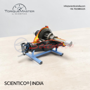
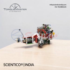
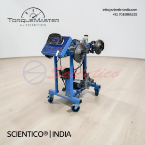
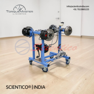
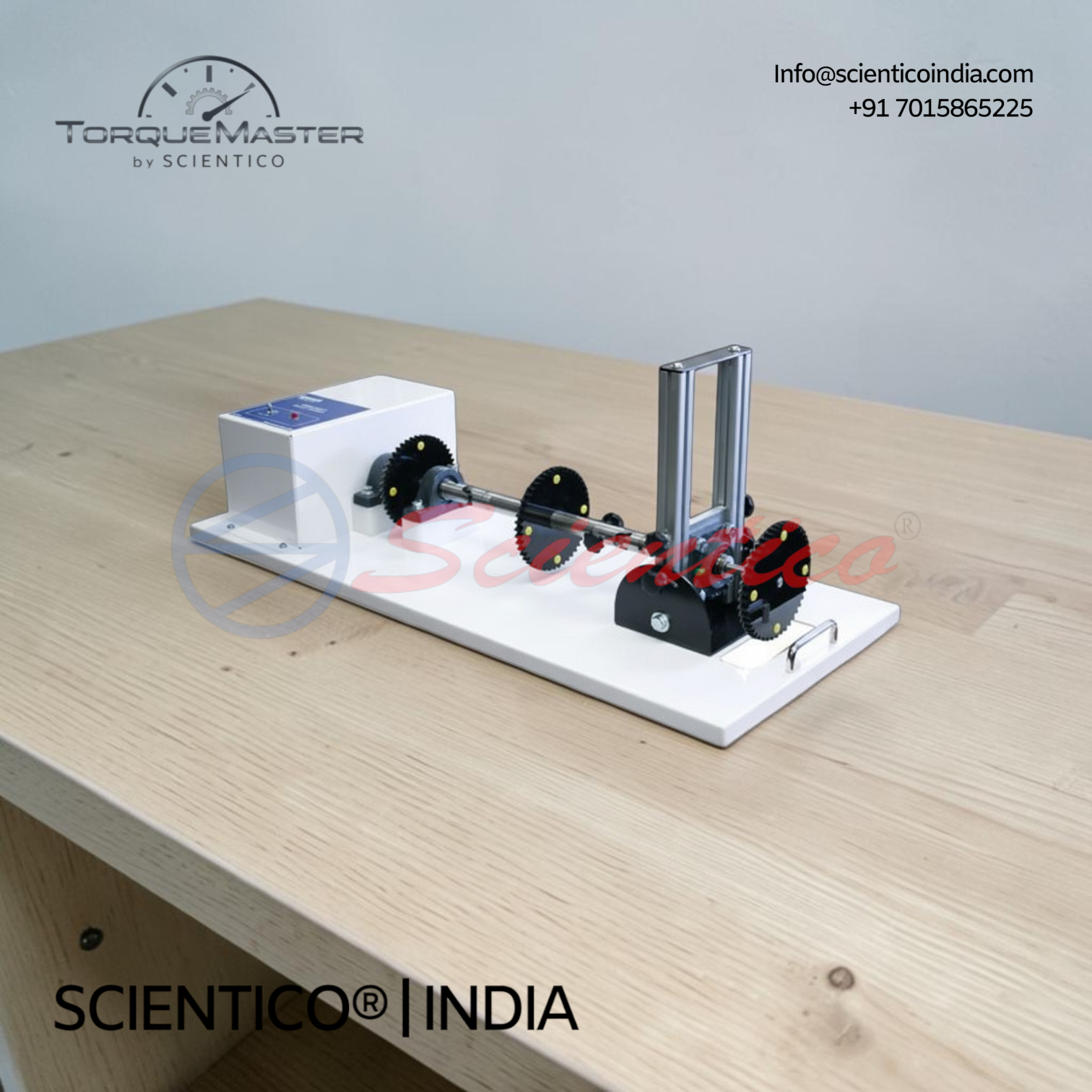
Working Model Of Drive Shaft Torquemaster-12 demonstrates the acceleration and deceleration phenomenon that occurs in revolving universal joints and drive shafts at various angles. This Working Model Of Drive Shaft is driven by an electric motor with universal shaft adjustment, allowing different driveshaft angles to be selected. Speed variation effects are audibly demonstrated using toothed wheels, illustrating vibration and wear caused by angled operation. It is mounted on a mobile solid frame for classroom demonstration.
The Working Model Of Drive Shaft Torquemaster-12 demonstrates and simplifies the complex acceleration and deceleration phenomenon that occurs in revolving universal joints and drive shafts operating at various angles. This Working Model Of Drive Shaft shows how output speed varies even when the input driveshaft rotates at a constant speed.
Product Overview
The Torquemaster-12 demonstrates that even when the input driveshaft rotates at constant speed, the output driveshaft maintains a variable speed depending on the angle between them, which causes vibrations and wear over time. The higher the angle between the shafts, the more amplified this effect becomes. The model illustrates the propeller shaft, sometimes called a carden shaft, which transmits power from the gearbox to the rear axle. This Working Model Of Drive Shaft shows that the shaft normally has a tubular section and is made in one- or two-piece construction, with the two-piece arrangement supported at the mid point by a rubber-mounted bearing. Short drive shafts are also represented, used for transmitting power from the final drive assembly to the road wheels in both front and rear wheel drive layouts.
Planning an automobile lab? See the automobile engineering equipment and model-selection guide.
Working Model Of Drive Shaft Torquemaster-12 — Technical Specifications
| Parameter | Value |
|---|---|
| Model | Torquemaster-12 |
| System Type | Fully functional Drive Shaft system installed in a mobile solid frame |
| Angle Adjustment | Different driveshaft angles can be selected using the adjustment system |
| Speed Change Demonstration | Results of changes in speed audibly demonstrated using toothed wheels |
| Power Required | 230V, 50Hz, 1 phase |
| Length x Width x Height (approx.) | 800 x 500 x 600 mm |
| Weight (approx.) | 45 kg |
Technical Data
| Component | Detail |
|---|---|
| Drive Method | Driven by electric motor |
| Indicators | Visual indicators |
| Shaft Adjustment | Universal shaft adjustment |
| Propeller Shaft | Tubular section, one- or two-piece construction |
| Two-Piece Support | Supported at mid point by rubber-mounted bearing |
| Short Drive Shafts | Transmit power from final drive assembly to road wheels in front and rear wheel drive layouts |
Key Features
- Drive Method: Driven by electric motor
- Indicators: Visual indicators for speed and angle effects
- Adjustment: Universal shaft adjustment
- Angle Selection: Different driveshaft angles selectable via adjustment system
- Audible Demonstration: Speed changes demonstrated audibly using toothed wheels
- Design Type: Working Model Of Drive Shaft mounted in a mobile solid frame for classroom use
Experiments
- Study of acceleration and deceleration in revolving universal joints
- Study of variable output speed at different driveshaft angles
- Observation of vibration and wear effects caused by angle changes
- Study of propeller shaft construction, one-piece and two-piece
- Study of short drive shaft power transmission in front and rear wheel drive layouts
- Audible demonstration of speed variation using toothed wheels
Construction and Design
The Working Model Of Drive Shaft Torquemaster-12 is a fully functional drive shaft system installed in a mobile solid frame. It is driven by an electric motor and fitted with visual indicators to demonstrate the effects of shaft angle on output speed. The universal shaft adjustment allows different driveshaft angles to be selected, and the resulting speed changes can be audibly demonstrated using toothed wheels. The model represents the propeller shaft, or carden shaft, along with short drive shafts used in the transmission of power to the road wheels.
Scope of Delivery
- Drive shaft system on mobile solid frame
- Electric motor drive unit
- Universal shaft adjustment mechanism
- Toothed wheel speed demonstration assembly
- Visual indicators
Required for Operation
- Power supply: 230V, 50Hz, 1 phase
Q1: What does the Working Model Of Drive Shaft Torquemaster-12 demonstrate?
A: It demonstrates the acceleration and deceleration phenomenon in revolving universal joints and drive shafts operating at various angles.
Q2: Why does output driveshaft speed vary?
A: Even when the input driveshaft rotates at constant speed, the output driveshaft maintains a variable speed depending on the angle between them, causing vibrations and wear.
Q3: How is the speed variation demonstrated?
A: The results of speed changes are audibly demonstrated using toothed wheels.
Q4: What power supply does this model require?
A: It requires a 230V, 50Hz, 1 phase power supply.
Q5: What are the dimensions and weight of the model?
A: The approximate dimensions are 800 x 500 x 600 mm, with an approximate weight of 45 kg.
Need Assistance? We're Here to Help!
Connect with our team for product specifications, pricing, and customized solutions for your institution or project.