
Impact Testing Machine and Torsion Testing Machine: Experiments, Procedure and Calculations
The impact test and torsion test are two essential experiments in the Strength of Materials and Materials Science laboratory, complementing the UTM tensile test. They measure material properties under dynamic loading (impact) and twisting loads (torsion) that cannot be determined from a static tensile test alone. This guide covers both experiments with complete theory, procedure, observation tables, and calculations for engineering lab reports.
Equipment mentioned in this guide
Review the product information, specifications and model before requesting a quotation.
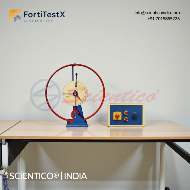
Impact Testing Machine | FortiTestX – 15
Impact Testing Machine FortiTestX 15 is a benchtop strength of materials lab equipment unit designed for notched bar impact bending tests on metallic and non-metallic specimens. This Impact Testing Machine operates on the pendulum principle, delivering a hammer impact speed of 3.8 m/s and a maximum work capacity of 25 Nm, with impact energy read directly from the gauge on a large scale. The FortiTestX 15 supports U, V, and keyhole notch configurations across four specimen materials, making it a complete impact testing machine strength of materials lab equipment unit for undergraduate material testing programmes.
View product details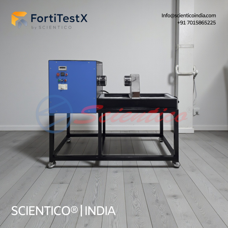
Torsion Testing Machine 1000Nm (Motorized) | FortiTestX – 12
Torsion Testing Machine FortiTestX 12 is a motorised, benchtop strength of materials lab equipment unit engineered for torsional testing of various material specimens to fracture under a maximum test torque of 1000 Nm. This Torsion Testing Machine 1000Nm Motorized apparatus applies torque via a motor-driven worm gear reduction mechanism, measuring test torque through a strain gauge shaft and angle of twist through an incremental encoder, with both values displayed simultaneously on digital readouts within a microprocessor-based enclosure. The FortiTestX 12 accommodates specimen lengths up to 650 mm via a sliding measurement jig and accepts specimens of different diameters through a jaw-type holder, making it the highest-capacity torsion testing machine 1000Nm motorized unit in the FortiTestX range for undergraduate and research-level engineering laboratories.
View product detailsPart A: Impact Test, Charpy and Izod
Objective
- To determine the impact energy absorbed by a standard notched specimen during fracture using the Charpy or Izod test.
- To assess material toughness (energy absorbed per unit cross-sectional area of notch).
- To compare impact toughness of different materials (mild steel, cast iron, aluminium, brass, polymers).
Theory
Impact energy E = mgh1 – mgh2 = mg(h1 – h2), where m = pendulum mass, h1 = initial height, h2 = final height after fracture, g = 9.81 m/s squared.
Charpy test: specimen supported as a beam at both ends (simply supported), struck at mid-span. Notch faces away from the striker. Izod test: specimen clamped vertically (cantilever), struck 22 mm above the notch. Notch faces the striker.
Impact toughness = Energy absorbed / Cross-sectional area at notch (J/m squared or kJ/m squared)
Procedure
- Measure specimen dimensions at the notch cross-section: width b (mm) and height at notch d (mm). Calculate notch cross-section area A = b x d.
- For Charpy test: position the specimen on the anvil supports, notch centred and facing away from the hammer. For Izod: clamp specimen vertically in the vice, notch at the specified height, facing the hammer.
- Raise the pendulum to the initial angle and latch it. Read and record the initial angle alpha1 on the scale.
- Release the pendulum. It strikes the specimen and swings through to angle alpha2 on the other side.
- Read the final angle alpha2 from the scale pointer.
- Calculate: h1 = R(1 – cos alpha1), h2 = R(1 – cos alpha2), where R = pendulum radius. Energy absorbed = mg(h1 – h2). (Most machines show energy directly on a calibrated scale.)
- Repeat with different materials. Note fracture appearance: ductile (fibrous, dull grey) or brittle (crystalline, bright).
Observation Table, Impact Test
| Material | Notch Width b (mm) | Notch Height d (mm) | Area A (mm squared) | Initial angle (deg) | Final angle (deg) | Energy absorbed (J) | Toughness (kJ/m squared) | Fracture type |
|---|---|---|---|---|---|---|---|---|
| Mild steel | ||||||||
| Cast iron | ||||||||
| Aluminium |
Part B: Torsion Test
Objective
- To determine the modulus of rigidity G (shear modulus) of a given material.
- To determine the shear yield stress and ultimate shear strength.
- To plot the torque-twist (T-theta) diagram for the specimen.
Theory
Torsion formula: T/J = G x theta / L = tau / r
Where T = applied torque (N.m), J = polar second moment of area = pi x d^4 / 32 for solid circular section, G = modulus of rigidity (GPa), theta = angle of twist (radians), L = gauge length (m), tau = shear stress, r = radius.
Modulus of rigidity: G = (T x L) / (J x theta)
Procedure
- Measure specimen diameter d at three points along gauge length. Use minimum value. Calculate J = pi x d^4 / 32.
- Mark the gauge length L with punch marks. Record L.
- Mount the specimen in the hexagonal chucks of the torsion machine. Ensure firm grip with no slip.
- Set the torque and angle indicators to zero.
- Apply torque in increments (5-10 N.m steps for 10 mm diameter specimens). At each step, record torque T and angle of twist theta.
- Continue until fracture. Note the maximum torque (ultimate shear), the torque at which the T-theta curve deviates from linear (shear yield), and the fracture angle.
- Calculate G from the linear (elastic) region of the T-theta plot: G = (T x L) / (J x theta).
Observation Table, Torsion Test
Material: _____ | Diameter d = _____ mm | J = _____ mm^4 | Gauge length L = _____ mm
| Obs. | Torque T (N.m) | Angle of Twist theta (degrees) | theta (radians) | Shear Stress tau (MPa) | Modulus G (GPa) |
|---|---|---|---|---|---|
| 1 | |||||
| 2 | |||||
| 3 | |||||
| 4 | |||||
| 5 |
Related Experiments and Equipment
Perform alongside the UTM tensile test. Browse Scientico impact testing machine and torsion testing machine product pages. Full Strength of Materials lab equipment range. Country pages: UAE, Kenya, Bangladesh.
{“@context”:”https://schema.org”,”@type”:”HowTo”,”name”:”Impact Test and Torsion Test Procedure, Charpy, Izod, Torsion Machine”,”description”:”Combined procedure for conducting Charpy and Izod impact tests, and a torsion test to determine shear modulus of rigidity.”,”totalTime”:”PT2H”,”step”:[{“@type”:”HowToStep”,”position”:1,”name”:”Specimen Preparation”,”text”:”For impact test: machine Charpy V-notch specimen (10×10×55 mm) or Izod specimen (10×10×75 mm) per IS 1499. For torsion test: prepare circular cross-section specimen and measure gauge length and diameter.”},{“@type”:”HowToStep”,”position”:2,”name”:”Impact Test, Set Pendulum”,”text”:”Raise the pendulum to the standard height and lock. For Charpy: place specimen horizontally on supports with notch facing the striker. For Izod: clamp vertically with notch facing the striker.”},{“@type”:”HowToStep”,”position”:3,”name”:”Release and Record”,”text”:”Release the pendulum. Record the angle of swing after fracture. Calculate absorbed energy: E = W × R × (cosβ – cosα), where W = pendulum weight, R = pendulum radius.”},{“@type”:”HowToStep”,”position”:4,”name”:”Compare Materials”,”text”:”Test specimens of mild steel, cast iron, and copper. Record absorbed energy for each. Compare brittle (low energy) vs ductile (high energy) fracture behavior.”},{“@type”:”HowToStep”,”position”:5,”name”:”Torsion Test Setup”,”text”:”Fix the torsion testing machine specimen. Apply torque gradually using the calibrated torque head. Record torque (T) and angle of twist (θ) at regular intervals.”},{“@type”:”HowToStep”,”position”:6,”name”:”Calculate Shear Modulus”,”text”:”Calculate modulus of rigidity: G = TL / (Jθ), where L = gauge length, J = polar moment of inertia = πd⁴/32, θ in radians.”},{“@type”:”HowToStep”,”position”:7,”name”:”Plot Torque-Twist Diagram”,”text”:”Plot T vs θ. Identify the linear elastic region and yield torque. Report G value and compare with standard values (steel: 80 GPa, copper: 40 GPa).”}]}Get Specifications & Pricing
Scientico India manufactures laboratory apparatus under an ISO 9001:2015 quality system. Conformity documentation is confirmed for each quoted model. Contact us for full specifications, pricing, and documentation.
WhatsApp: +91 701-586-5225 | [email protected] | FAQ, Shipping, Payment & Warranty
Scientico India manufactures this and the full range of Strength of Materials equipment, model-specific and supplied to engineering colleges worldwide.
Explore Strength of Materials Equipment → or request a quoteOne honest ask
We don't gate anything on this site. You just read the whole thing free. If it was useful, leave your email and two things happen: we send you this page as a plain-text block you can paste into a tender file or an internal email, and we notify you the next time we publish a buyer tool like this one. Nothing else. No drip sequence, no sales calls booked without asking.