Two Shaft Gas Turbine Study Apparatus | ThermoFlux – 7087
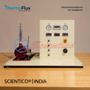
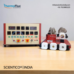
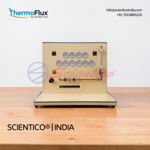
The Two Shaft Gas Turbine Study Apparatus ThermoFlux – 7087 is a wheeled, laboratory-scale training unit for the study of gas turbine operation in a two-shaft configuration. This two shaft gas turbine trainer covers the complete Joule-Brayton cycle, with a turbocharger assembly (30,000 to 90,000 rpm), a power turbine (2,000 to 23,000 rpm), a propane/butane LPG combustion chamber, and a 1 kW alternator on a single steel frame. Five temperature points, six pressure points, two shaft speed measurements, and generator electrical output are all displayed on a mimic diagram panel. The unit is available in manual and computerized versions, with optional LABVIEW-based DAQ software for automated data acquisition and analysis.
The Two Shaft Gas Turbine Study Apparatus ThermoFlux – 7087 is a laboratory-scale, wheeled training unit built for hands-on study of gas turbine operation in a two-shaft configuration. This two shaft gas turbine trainer replicates a real Joule-Brayton cycle at reduced scale, with a turbocharger assembly, power turbine, combustion chamber, and alternator mounted on a single base frame. Students gain direct exposure to gas turbine starting procedures, thermodynamic cycle analysis, and electrical power generation from turbine output.
Product Overview
The ThermoFlux – 7087 consists of a wheeled steel frame, a mimic diagram panel carrying all measurement instruments, and a base supporting the core components: combustion chamber, turbocharger assembly, power turbine, and alternator. Exhaust gases from combustion of compressed air and propane/butane LPG gas expand first through the turbocharger turbine, supplying energy to compress incoming air, and then through the power turbine. The power turbine, operating between 2,000 and 23,000 rpm, drives the alternator via a toothed belt. The alternator produces 1 kW at 3,300 rpm, and generated electrical energy is dissipated through a resistive load.
The turbocharger assembly operates between 30,000 and 90,000 rpm at a compression ratio of approximately 2:1. An auxiliary starting fan initiates the high-pressure turbine, and effective silencing at intake and exhaust makes the unit suitable for laboratory environments. The lubrication system includes a 20-litre oil tank, oil pump, oil filter, and a water/oil heat exchanger. Cooling water is supplied from laboratory mains.
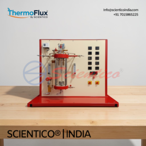
The unit is available in two versions. The manual version uses digital meters, analog pressure gauges, and direct instrument displays on the mimic panel. The computerized version adds signal converters on all measurement instruments, a feeding and A/D conversion unit, a gas flow meter, a U-manometer, and data acquisition and analysis software. All sensors record data visualized on displays within the process schematic.
The optional ThermoFlux – 7087 DAQ software is developed in the National Instruments LABVIEW environment and is compatible with any Windows operating system.
Two Shaft Gas Turbine Study Apparatus ThermoFlux – 7087, Technical Specifications
| Parameter | Value |
|---|---|
| Model | ThermoFlux – 7087 |
| Configuration | Two-shaft gas turbine |
| Frame | Wheeled steel frame with mimic diagram panel |
| Combustion Chamber Fuel | Propane/butane LPG gas from cylinder |
| Turbocharger Speed Range | 30,000 to 90,000 rpm |
| Compression Ratio | Approx. 2:1 |
| Power Turbine Speed Range | 2,000 to 23,000 rpm |
| Alternator Output | 1 kW at 3,300 rpm |
| Power Turbine to Alternator Drive | Toothed belt |
| Electrical Load | Resistive load |
| Oil Tank Capacity | 20 litres |
| Lubrication | Oil pump, oil filter, water/oil heat exchanger |
| Starting Device | Auxiliary starting fan |
| Silencing | Effective silencing at intake and exhaust |
| Electric Supply | 220/380 V three-phase, 50 to 60 Hz, 3 kW |
| Gas Supply | Propane/butane LPG from cylinder, 5 bar minimum |
| Water Supply | Laboratory mains |
| Software (Optional) | DAQ software, National Instruments LABVIEW, Windows compatible |
| Scope of Delivery | 1 experimental unit, 1 instruction manual |
Technical Data
Power Turbine
| Parameter | Value |
|---|---|
| Speed Range | 2,000 to 23,000 rpm |
| Drive to Alternator | Toothed belt |
| Alternator Output | 1 kW at 3,300 rpm |
Turbocharger Assembly
| Parameter | Value |
|---|---|
| Speed Range | 30,000 to 90,000 rpm |
| Compression Ratio | Approx. 2:1 |
Combustion Chamber
| Parameter | Value |
|---|---|
| Fuel | Propane/butane LPG gas from cylinder |
| Ignition | Spark plug |
| Gas Flow Control | Gas flow rate regulation valve |
Lubrication System
| Parameter | Value |
|---|---|
| Oil Tank Capacity | 20 litres |
| Oil Pump | Included |
| Oil Filter | Included |
| Cooling | Water/oil heat exchanger |
| Oil Pressure Monitoring | Pressure gauge for lubricating oil pressure control |
Instrumentation, Manual Version
| Instrument | Type |
|---|---|
| Ammeter | Digital |
| Voltmeter | Digital |
| RPM Meters | Digital |
| Temperature Indicators | Digital |
| Pressure Gauges | Analog |
Instrumentation, Computerized Version
| Instrument | Type |
|---|---|
| Ammeter | Digital with signal converter |
| Voltmeter | Digital with signal converter |
| RPM Meters | Digital with signal converter |
| Pressure Gauges | With pressure/current converter |
| Gas Flow Meter | Included |
| U-Manometer | Included |
| A/D Conversion Unit | Feeding, signal conditioning, and A/D conversion |
| Data Acquisition Software | National Instruments LABVIEW, Windows compatible |
Measurement Points (Mimic Diagram)
| Label | Measurement | Unit |
|---|---|---|
| T1 | Air temperature, inlet | °C |
| T2 | Compressed air temperature | °C |
| T3 | Combustion chamber temperature | °C |
| T4 | Turbocharger outlet / power turbine inlet temperature | °C |
| T5 | Exhaust temperature | °C |
| P2 | Compressor outlet pressure | kPa |
| P3 | Combustion chamber pressure | kPa |
| P4 | Turbocharger outlet / power turbine inlet pressure | kPa |
| P5 | Exhaust pressure | kPa |
| PB | LPG/propane gas pressure | kPa |
| P6 | LPG/propane regulated gas pressure | kPa |
| V | Generator voltage | V |
| I | Generator current | A |
| nGG | Turbocharger speed | rpm |
| nTP | Power turbine speed | rpm |
| Qg | Gas flow rate (gas flow meter) | – |
| Qa | Air flow (orifice meter) | – |
| S | Oil pressure gauge | – |
Required Services
| Service | Requirement |
|---|---|
| Electric Supply | 220/380 V three-phase, 50 to 60 Hz, 3 kW |
| Gas Supply | Propane/butane LPG from cylinder, 5 bar minimum |
| Water Supply | Laboratory mains |
Key Features
- Configuration: Two-shaft gas turbine, power turbine separate from turbocharger shaft
- Turbocharger Speed: 30,000 to 90,000 rpm, compression ratio approx. 2:1
- Power Turbine Speed: 2,000 to 23,000 rpm, toothed belt drive to alternator
- Alternator Output: 1 kW at 3,300 rpm, electrical energy dissipated on resistive load
- Combustion Fuel: Propane/butane LPG gas from cylinder, 5 bar minimum supply
- Two Shaft Gas Turbine Starting: Auxiliary starting fan initiates the high-pressure turbine
- Lubrication: Oil pump, oil filter, 20-litre oil tank, water/oil heat exchanger
- Silencing: Effective intake and exhaust silencing for safe indoor laboratory operation
- Mimic Diagram Panel: All sensors visualized on process schematic with measurement displays
- Measurement Points: 5 temperature points (T1 to T5), 6 pressure points (P2 to P6, PB), generator voltage and current, two speed measurements, gas and air flow rates
- Manual Version: Digital meters for temperature, RPM, voltage, current; analog pressure gauges
- Computerized Version: Signal converters on all instruments, gas flow meter, U-manometer, A/D conversion unit, LABVIEW-based DAQ software
- Frame: Wheeled steel frame for easy laboratory repositioning
- Optional Software: National Instruments LABVIEW DAQ software, Windows compatible
Experiments
- Study of a Joule-Brayton cycle
- Study on a reduced scale of a plant for the production of electrical energy by a gas turbine
- Study of the starting procedure of a gas turbine
- Measurement of the air flow input as a function of the speed of the turbocharger
- Pressure and temperature in the combustion chamber as a function of the speed of the turbocharger
- Calculation of the specific consumption as a function of the speed of the turbocharger
- Calculation of the output power as a function of the speed of the power turbine
- Determination of the power output with different input parameters
- Study of safety systems in the operation of a gas turbine
Construction and Design
The Two Shaft Gas Turbine Study Apparatus ThermoFlux – 7087 is built on a wheeled steel frame, allowing easy repositioning within a laboratory. The base supports the combustion chamber, turbocharger assembly, power turbine, and alternator as a compact, integrated unit. A front-facing mimic diagram panel carries all measurement instruments, giving students a clear visual representation of the process flow.
The two shaft gas turbine arrangement separates the turbocharger shaft from the power turbine shaft. Combustion gases first expand through the turbocharger turbine to drive the compressor, then pass through the power turbine to generate shaft work. The power turbine connects to the alternator via a toothed belt. Generated electricity is fed to a resistive load for dissipation.
The combustion chamber burns propane/butane LPG gas supplied from a cylinder. A spark plug provides ignition. A gas flow rate regulation valve controls fuel supply, and a gas flow meter (computerized version) measures fuel consumption. Air enters through an air filter. An orifice meter measures air flow. An auxiliary starting fan initiates rotation of the high-pressure turbocharger stage before combustion begins.
The lubrication circuit consists of an oil pump, oil filter, 20-litre oil tank, and a water/oil heat exchanger cooled by laboratory mains water. Oil pressure is monitored by a dedicated pressure gauge. Intake and exhaust silencing is built into the unit for safe indoor operation. A gas exhaust duct channels combustion products out of the working area.
All measurement points, covering five temperatures, six pressures, generator voltage, generator current, two shaft speeds, and gas and air flow rates, are displayed on the mimic diagram panel. In the computerized version, signal converters on each instrument feed data to a feeding and A/D conversion unit for software acquisition and analysis.
Software
ThermoFlux – 7087 DAQ Software (Optional)
The optional data acquisition software for the two shaft gas turbine apparatus is developed in the National Instruments LABVIEW environment. It measures and calculates results from all apparatus sensors. The software runs on any Windows operating system. When the software option is selected, a set of electronic sensors with signal converters is included.
Scope of Delivery
- 1 experimental unit
- 1 instruction manual
Required for Operation
- Electric supply: 220/380 V three-phase, 50 to 60 Hz, 3 kW
- Propane/butane LPG gas supply: from cylinder, 5 bar minimum
- Water supply: from laboratory mains
Optional Accessories
- ThermoFlux – 7087 DAQ software (National Instruments LABVIEW, Windows compatible), including electronic sensors with signal converters
- Gas type pre-mixed burner (if applicable; specify at time of order)
Q1: What is the difference between the manual and computerized versions of the ThermoFlux – 7087?
The manual version uses digital meters and analog pressure gauges with direct display on the mimic panel. The computerized version adds signal converters on all instruments, a gas flow meter, a U-manometer, an A/D conversion unit, and LABVIEW-based data acquisition software for automated measurement and analysis.
Q2: What fuel does the two shaft gas turbine apparatus use?
The combustion chamber uses propane/butane LPG gas supplied from a cylinder. The gas supply pressure must be a minimum of 5 bar.
Q3: How is the power turbine connected to the alternator?
The power turbine is coupled to the alternator by a toothed belt. The alternator generates 1 kW at 3,300 rpm, and the power turbine operates between 2,000 and 23,000 rpm.
Q4: What safety systems are included on the ThermoFlux – 7087?
The unit includes an emergency switch, gas flow control and regulation valves, oil pressure monitoring, and effective intake and exhaust silencing. The apparatus also supports a dedicated experiment on gas turbine safety systems.
Q5: Is the ThermoFlux – 7087 DAQ software compatible with standard laboratory computers?
Yes. The optional DAQ software runs in the National Instruments LABVIEW environment and is compatible with any Windows operating system.
Need Assistance? We're Here to Help!
Connect with our team for product specifications, pricing, and customized solutions for your institution or project.