
Aim: To verify Bernoulli’s theorem and determine the velocity of flow at different cross-sections of a converging-diverging passage connected to a hydraulic bench.
Equipment mentioned in this guide
Review the product information, specifications and model before requesting a quotation.
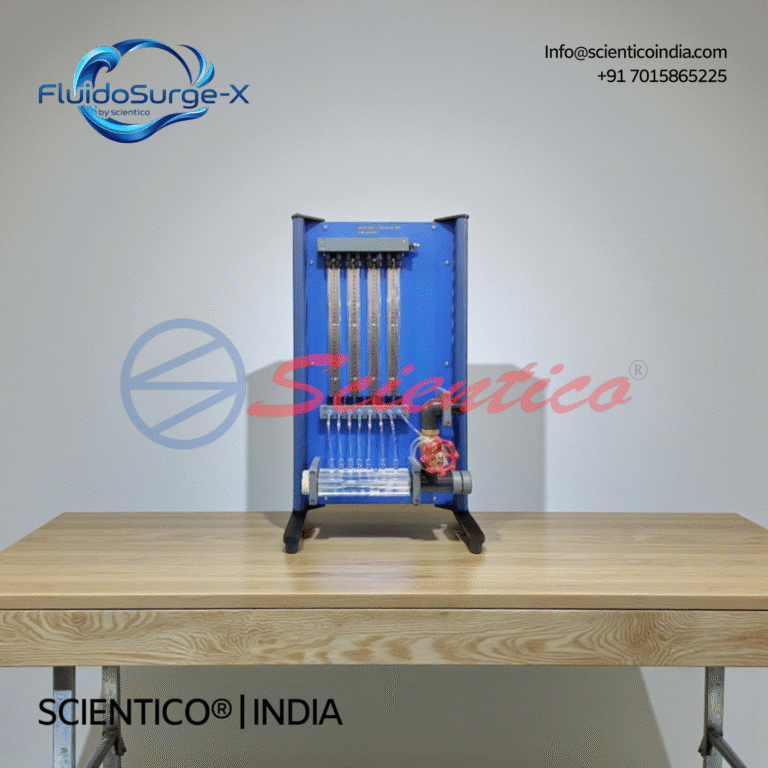
Bernoulli’s Theorem Apparatus | FluidoSurge-X 120
The Bernoulli's Theorem Apparatus FluidoSurge-X 120 is designed for experimental verification of Bernoulli’s principle in fluid mechanics laboratories. It enables detailed study of pressure, velocity, and energy variations along a converging and diverging duct. The apparatus uses a transparent Venturi test section with multiple pressure tapping points. It is intended for structured academic experiments and analytical comparison with theoretical flow behavior.
View product details
Hydraulic Bench Apparatus | FluidoSurgeX 101
The SCIENTICO FluidoSurgeX 101 Hydraulic Bench Apparatus is a basic supply and measurement unit used in fluid mechanics laboratories. It enables the circulation, measurement, and collection of water for a wide range of experimental modules.The system operates on a closed-loop water circuit consisting of a storage tank, centrifugal pump, and an elevated measuring tank. Volumetric flow rates are determined using stepped measuring tanks and a calibrated measuring beaker, supported by manual stopwatch timing.An integrated work surface with a built-in flume allows experiments involving weirs while ensuring safe placement of accessories and controlled collection of return water.
View product detailsApparatus Required
- Bernoulli Theorem Apparatus (convergent-divergent duct with piezometer tappings)
- Hydraulic Bench (flow supply and measurement)
- Stopwatch
- Measuring tape / vernier caliper
Theory
Bernoulli’s theorem states that for steady, incompressible, non-viscous flow along a streamline, the total energy per unit weight remains constant: P/ρg + V²/2g + z = constant, where P/ρg is pressure head, V²/2g is velocity head, and z is datum head. In a converging duct, velocity increases and pressure decreases; in a diverging section, velocity decreases and pressure recovers.
Procedure
- Set up the Bernoulli apparatus on the hydraulic bench. Connect the inlet and outlet to the bench supply and measuring tank.
- Open the inlet valve slowly to allow water to flow through the convergent-divergent duct. Remove all air bubbles from piezometer tubes by gently tapping.
- Adjust the flow control valve to set a steady flow rate. Measure the flow rate using the volumetric measuring tank and stopwatch (Q = V/t).
- Record the piezometric (static pressure) head at each tapping point h₁ through h₈.
- Calculate the velocity at each section using the continuity equation: V = Q/A, where A is the cross-sectional area at each tapping.
- Calculate the velocity head: V²/2g at each section.
- Calculate total head H = h + V²/2g at each section.
- Repeat for two more flow rates (medium and high).
Observation Table
| Tapping No. | Diameter (mm) | Area (cm²) | Piezometric Head h (cm) | Velocity V (cm/s) | Velocity Head V²/2g (cm) | Total Head H (cm) |
|---|---|---|---|---|---|---|
| 1 (inlet) | 25 | – | – | – | – | – |
| 2 | 22 | – | – | – | – | – |
| 3 (throat) | 14 | – | – | – | – | – |
| 4 | 18 | – | – | – | – | – |
| 5 (exit) | 25 | – | – | – | – | – |
Calculations
Flow rate: Q = Volume / Time (m³/s)
Velocity at section n: Vₙ = Q / Aₙ
Velocity head: Vₙ²/2g
Total head: Hₙ = hₙ + Vₙ²/2g
Theorem verification: If H₁ ≈ H₂ ≈ H₃ ≈ … ≈ Hₙ (within ±5%), Bernoulli’s theorem is verified.
Results and Precautions
The total head at all sections should be approximately constant, confirming Bernoulli’s theorem. Minor variation is due to friction losses. Precautions: Ensure no air bubbles in piezometer tubes; maintain steady flow before recording; use the same datum for all head measurements.
Frequently Asked Questions
What is the principle behind Bernoulli’s theorem experiment?
Bernoulli’s theorem states that in steady, incompressible flow, the sum of pressure head, velocity head, and datum head is constant along a streamline. The experiment verifies this by measuring static pressure heads at sections of different cross-sectional areas, where the pipe narrows (throat), velocity increases and pressure decreases.
Why does pressure decrease at the throat in Bernoulli’s apparatus?
By the continuity equation, velocity must increase as the cross-sectional area decreases. By Bernoulli’s equation, an increase in velocity head must be compensated by a decrease in pressure head (for constant total head). This is observed as a drop in the piezometer reading at the throat.
What is the Bernoulli theorem apparatus used for in engineering labs?
The Bernoulli theorem apparatus is used in fluid mechanics labs to experimentally verify the Bernoulli equation, understand the relationship between pressure and velocity in pipe flow, and develop skills in flow measurement and piezometric head reading.
Get Fluid Mechanics Lab Equipment
Scientico India manufactures ISO 9001:2015 and model-specific fluid mechanics lab apparatus. Contact us for specifications and CIF pricing.
Scientico India manufactures this and the full range of Fluid Mechanics Lab equipment, model-specific and supplied to engineering colleges worldwide.
Explore Fluid Mechanics Lab Equipment → or request a quote