
Equipment mentioned in this guide
Review the product information, specifications and model before requesting a quotation.
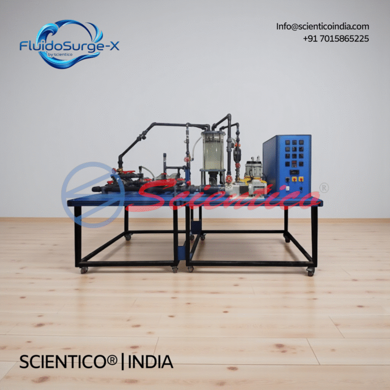
Advance Multi Pump Test Rig | FluidoSurge-X 342
The Advance Multi Pump Test Rig FluidoSurge-X 342 is a comprehensive laboratory system designed for in-depth study of operating characteristics of multiple pump types. Manufactured by SCIENTICO, this fully instrumented bench allows precise measurement and analysis of hydraulic, mechanical, and performance parameters of pumps under controlled conditions. It is intended for advanced teaching and experimental work in fluid mechanics laboratories.
View product details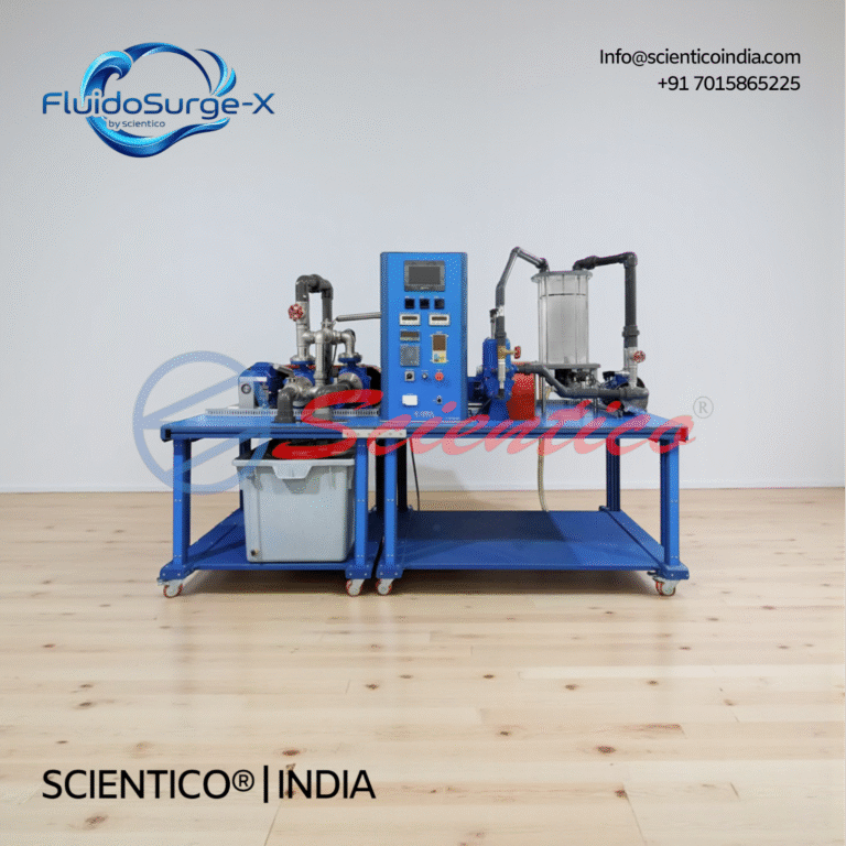
Multi Pump Test Rig with 4 Pumps | FluidoSurge-X 345
The Multi Pump Test Rig with 4 Pumps FluidoSurge-X 345 is an advanced laboratory system designed for detailed study of pump operating characteristics. Manufactured by SCIENTICO, this fully instrumented bench enables experimental analysis of centrifugal, side channel, and positive displacement pumps under controlled conditions.
View product detailsWhat a hydraulic machinery lab has to contain, and why
A fluid mechanics and hydraulic machinery lab exists to let a student see energy move between a fluid and a rotating shaft, in both directions. Turbines take energy out of the water. Pumps put energy in. Everything else in the room is measurement.
That is the whole logic of the rig list. If a department buys the rigs without asking which direction of energy transfer each one demonstrates and which curve the student is expected to plot, it ends up with a room full of machines that run but do not teach.
Here is the short answer before the detail. These are the rigs that carry almost every syllabus at degree and diploma level.
| Rig | What it demonstrates | The experiment a student actually performs |
|---|---|---|
| Pelton wheel test rig | Impulse action, jet striking buckets at atmospheric pressure | Load the wheel at fixed head and gate, plot power and efficiency against speed |
| Francis turbine test rig | Radial inward reaction, pressure drop across the runner, draft tube recovery | Vary guide vane opening and load, plot efficiency against unit speed |
| Kaplan turbine test rig | Axial reaction at low head and high flow, adjustable blade behaviour | Run constant head, vary load, plot the characteristic and compare with the Francis result |
| Centrifugal pump test rig | Rotodynamic head generation, priming dependence | Throttle the delivery at constant speed, plot head, power and efficiency against discharge |
| Reciprocating pump test rig | Positive displacement, near constant volume per revolution, slip | Vary delivery pressure, measure actual against theoretical discharge, calculate slip |
| Gear pump and vane pump rigs | Positive displacement in oil, volumetric efficiency falling with pressure | Load the circuit through a relief valve, plot volumetric and overall efficiency against pressure |
| Multi-pump rig, series and parallel | How two identical pumps combine, and why the gain is never double | Run single, series and parallel, superimpose the three curves on one system resistance curve |
| Hydraulic ram | Pumping without external power, using the pressure surge from a stopped column of water | Measure supply and delivery quantities, calculate D’Aubuisson and Rankine efficiencies |
Fluid mechanics is usually the largest single category in a mechanical department and it is shared with civil. If you are building the whole room rather than replacing one rig, work from the full mechanical engineering lab list and cross-check the overlap with the civil department list before you split the budget between two heads.
Turbine test rigs compared
This is the table both students and purchase committees want, and it is the one most supplier pages leave out. Get the impulse and reaction distinction right and half the syllabus explains itself.
| Turbine | Head regime | Flow regime | Runner action | Flow direction | Student measures | Student plots |
|---|---|---|---|---|---|---|
| Pelton wheel | High head | Low flow | Impulse. All pressure energy converted to velocity in the nozzle before the jet reaches the bucket. Runner works at atmospheric pressure | Tangential | Supply pressure, discharge, spear or nozzle setting, brake load, speed | Power against speed, efficiency against speed, unit power and unit speed |
| Francis turbine | Medium head | Medium flow | Reaction. Pressure falls across the runner as well as the guide vanes, so the runner is full of water and under pressure throughout | Radial inward, discharging axially | Inlet and outlet pressure, discharge, guide vane opening, load, speed | Main characteristic at constant head, operating characteristic at constant speed |
| Kaplan turbine | Low head | High flow | Reaction. Same pressure drop across the runner as Francis, with a propeller runner and, on adjustable machines, blade pitch that follows the load | Axial | Inlet head, discharge, load, speed, blade angle where adjustable | Efficiency against part load, compared with Francis to show why Kaplan holds efficiency at low load |
Three points I would insist on in the specification.
The Pelton rig needs a spear valve or an equivalent nozzle control that a student can actually set and read. Without it the jet is fixed and the whole family of curves at different gate openings disappears from the practical.
The Francis and Kaplan rigs need a real draft tube with a tapping. Draft tube pressure recovery is a reaction turbine idea, and if there is no read point the student cannot show that the pressure at runner exit is below atmospheric.
Every turbine rig needs a loading arrangement the student can vary in small steps and read directly. A rope brake or brake drum with spring balances is transparent and cheap to maintain. Electrical loading through a generator and a resistance bank is cleaner and repeats better, and it also gives you an electrical output reading for comparison with mechanical output. Both are defensible. What is not defensible is a rig where the load can only be set to two or three coarse positions, because then the characteristic curve is three dots and a guess.
Pump test rigs compared
| Pump | Class | Flow against head behaviour | Priming | Pressure pulsation | Student plots |
|---|---|---|---|---|---|
| Centrifugal | Rotodynamic | Variable flow. Discharge falls as head rises, along a continuous curve | Required. The casing and suction line must be full of liquid before starting | Low, steady delivery | Head, shaft power and efficiency against discharge at constant speed |
| Reciprocating | Positive displacement | Near constant volume per revolution. Discharge is almost independent of head, and pressure rises until something gives | Self priming in normal arrangements | High. Needs an air vessel to smooth delivery and reduce acceleration head | Actual against theoretical discharge, percentage slip, efficiency against delivery pressure |
| Gear | Positive displacement | Near constant volume, internal leakage grows with pressure | Self priming | Moderate, tooth meshing ripple | Volumetric efficiency and overall efficiency against delivery pressure |
| Vane | Positive displacement | Near constant volume, variable displacement on some designs | Self priming | Moderate | Same as gear, with the effect of displacement setting where applicable |
Priming, and why it is a teaching point rather than a footnote
A centrifugal pump generates head in proportion to the density of the fluid it is spinning. Air is roughly one eight hundredth the density of water, so an air filled impeller produces a pressure rise so small that it cannot lift water into the suction line. The pump runs, draws current, makes noise, and delivers nothing. Run it dry for long enough and the mechanical seal or gland goes, because the pumped liquid is also the coolant and lubricant for it.
A reciprocating pump does not have this problem because the piston physically sweeps a volume and will move air out of the way. That contrast is the cleanest way to teach the difference between the two classes, and it is worth specifying a transparent priming funnel and a suction gauge on the centrifugal rig so the student can see the vacuum build.
What a characteristic curve actually teaches
The curve is not decoration. It teaches four things at once: that a rotodynamic pump has one duty point only when it is matched to a system, that efficiency peaks at one discharge and falls either side, that shaft power for a centrifugal pump usually rises as the valve opens, and that the manufacturer’s curve is a statement about a specific speed and impeller diameter and stops being true when either changes.
The series and parallel rig extends this. Two pumps in series add head at the same flow. Two in parallel add flow at the same head. Neither doubles the duty point, because the system resistance curve is not flat, and watching a student discover that on their own plotted data is the single most useful hour in the module.
What to specify on a hydraulic test rig
Most disappointing rigs are not badly built. They are badly specified. The tender says “centrifugal pump test rig with all accessories” and the department gets whatever the lowest bidder decided that meant.
| Specification line | Write this | What goes wrong if you leave it vague |
|---|---|---|
| Sump and recirculation | Closed recirculating sump, stated volume, baffled or with settling section, drain point at the lowest level, accessible for cleaning | Undersized sump means the level drops during a run and readings drift. No drain means the tank is never cleaned and the impeller eats grit |
| Flow measurement | Name the method: collecting tank with piezometer and stopwatch, venturimeter, orifice plate, rotameter, or notch. State that the method must resolve the lowest flow in the experiment range | A rotameter sized for full flow cannot read the low flow end, so the interesting part of the curve is missing |
| Head measurement | Delivery pressure gauge and suction vacuum gauge on pumps, inlet and outlet tappings on turbines, gauge ranges stated, manometer where a differential is needed | An oversized gauge turns a real reading into an eyeball estimate |
| Loading and braking | Rope brake or brake drum with spring balances and cooling arrangement, or generator with a stepped resistive load bank. State that load must be variable in fine steps | Coarse loading gives too few points to plot a curve |
| Drive and speed | Motor rating and starter type, whether speed is fixed or variable, and how speed is read. Non-contact digital tachometer or mounted speed sensor | Without a speed reading, nothing can be reduced to unit quantities or corrected for speed |
| Electrical input | Energy meter or wattmeter on the motor supply so input power is measured, not assumed from nameplate rating | Efficiency calculated from nameplate power is fiction, and students learn a wrong habit |
| Read points | List every gauge and tapping and its location. Ask for a labelled schematic showing them | Instruments end up where they were easy to weld, not where the reading means something |
| Documentation | Experiment manual with worked sample calculation, calibration certificates, spare parts list with part identification | Faculty rewrite the manual themselves and the rig sits idle for a semester |
The test that decides a rig: can the student close an energy balance?
Before you accept any hydraulic rig, take the instrument list and try to complete the calculation on paper.
For a turbine you need water power at inlet, which requires flow and head, and shaft power at output, which requires speed and torque from the brake. Both must be available from instruments physically fitted to the rig. For a pump you need input power to the shaft, which in practice comes from measured electrical input with the motor efficiency stated, and output water power from flow and total head, where total head means the delivery reading plus the suction reading plus the datum difference, not the delivery gauge alone.
If any one term in that chain has no read point, the student cannot compute efficiency, and the practical degrades into recording numbers with no conclusion. I have seen this fail most often on the suction side of pump rigs and on the torque side of turbine rigs. Check those two first.
The same discipline applies when you are writing the specification document, and it is worth carrying into the wider tender document checklist that a government college has to satisfy.
Services and site readiness
Hydraulic rigs are the heaviest, wettest and noisiest equipment most engineering departments buy. Site readiness is the item institutions underestimate most consistently, and it is the reason commissioning slips.
| Service | Confirm before order | What happens if you do not |
|---|---|---|
| Water supply | A filling point near the rig position and a source of reasonably clean water for the initial fill and top ups | Buckets, spillage and a tank filled with whatever was nearest |
| Drainage | Floor gully or channel with adequate fall, at or near the rig, plus a route for draining the sump completely | Standing water, corroding frames and a lab that smells |
| Floor loading | Structural clearance for the filled mass of tank plus rig, especially above ground floor | Deflection under the frame, misalignment, vibration, disputes with the works department after installation |
| Levelling | Flat and level plinth or pads, with grouting or anchor provision where needed | Coupling misalignment, bearing failure, unrepeatable readings |
| Power | Three phase supply where required, correct rating, proper earthing, residual current protection, isolator within reach of the operator | Nuisance tripping, unsafe wet area electrics, motors run on the wrong supply |
| Noise | Reciprocating pumps and hydraulic rams are percussive. Consider position relative to classrooms and adjacent labs | The rig gets used only when the neighbouring room is empty, which means rarely |
| Splash containment | Drip trays, splash guards on open collecting tanks and notches, non slip floor treatment | Wet floors near live electrics, which is the most common real hazard in these labs |
| Access | Doorway and stair clearance for the largest single assembly, and space around the rig for a student group to stand and read gauges | Rig arrives and cannot be brought into the room |
If the lab is being built for accreditation review as well as teaching, capture the layout, the safety provisions and the utilisation records at the same time as installation. That evidence is far harder to reconstruct later, and the NBA lab documentation guide sets out what assessors ask to see.
Maintenance, wear and consumables
A hydraulic rig is not static equipment. It is a machine with rotating parts, running wet, operated by a new batch of students every few weeks who have never touched it before. Treat consumables as part of the purchase, not as a surprise in year two.
| Item | What wears it | Symptom to watch | Practical response |
|---|---|---|---|
| Mechanical seals and gland packing | Dry running, grit in the water, repeated starts | Drip at the shaft, then a steady leak, then a hot gland | Hold a set on the shelf, retighten or repack on schedule, never allow a dry start |
| Bearings | Misalignment, vibration, water ingress, long idle periods | Noise, heat, increased current draw | Check alignment after any move, log running hours, replace as a set |
| Impellers and wear rings | Suspended solids from an uncleaned sump, cavitation from a throttled suction | Head falls off the curve at the same speed and valve setting | Clean the sump on a schedule, never throttle the suction line to control flow |
| Pelton nozzle tip and spear | Jet erosion and any grit carried in the water | Jet spread, lower efficiency, curve shifted down | Inspect the tip annually, keep a spare nozzle and spear |
| Brake drum, rope and spring balances | Friction heat, students loading unevenly | Scored drum, frayed rope, balance that no longer returns to zero | Keep rope and balances as stocked spares, verify balance zero each session |
| Non-return and foot valves | Debris, seat wear | Loss of prime between sessions | Strip and clean, keep a spare valve |
| Gauges and manometers | Pulsation, over-range events, ageing | Reading that does not return to zero at rest | Include gauges in the periodic calibration list, use snubbers on pulsating lines |
| Reciprocating pump air vessel and piston packing | Cyclic duty | Rougher delivery, rising slip | Recharge or check the air vessel, repack on schedule |
Build these into a written schedule at handover rather than reacting to failures. The approach is set out in the calibration and maintenance schedule guide, and the commercial side, who holds stock and how fast a part reaches a campus, is covered in the note on spares and after sales support.
Standards, and what you can honestly cite
Be careful here, because tenders often demand a standard number for every line item and suppliers oblige by inventing one.
For the materials testing bench that usually sits in the same department, the citations are real and specific: tensile testing to IS 1608 or ISO 6892-1, Brinell to ASTM E10, Rockwell to ASTM E18, Vickers to ASTM E92, hardness conversion to ASTM E140, impact to IS 1757 and ASTM E23 for Charpy and IS 1598 for Izod. Soil work follows the IS 2720 series, cement the IS 4031 series, soil classification IS 1498 and concrete testing IS 516. Always confirm the current edition of any standard before you write it into a document, since these are revised.
For a hydraulic machinery teaching rig, write “the applicable test method” and state the quantities to be measured and the calculation the rig must support. That is honest and it is enforceable, which a fabricated standard number is not. Our wider IS and ASTM standards reference lists what belongs where, and the hardness tester buying guide shows the same discipline applied to a category where the standards genuinely are prescriptive.
Departments buying at diploma level should scale the rig list rather than copy the degree list wholesale. The polytechnic and diploma equipment list and the ITI trade-wise list both work from smaller footprints and simpler instrumentation, and the first year physics and chemistry list covers what should already exist before hydraulics arrives. If the fluid mechanics room is shared with civil, check it against the soil mechanics equipment list and the engineering mechanics list so nothing is ordered twice.
For distributors bidding hydraulic rigs into institutions
Hydraulic machinery rigs are good business for a distributor and bad business for an unprepared one. They are bulky, they need site work, and the buyer is a committee.
| Bid element | What decides the outcome |
|---|---|
| Technical compliance sheet | Answer every line of the specification in the buyer’s own wording and order. Committees score line by line and mark anything they cannot find as non-compliant |
| Manufacturer authorisation | Most institutional tenders require it, and it must match the tender reference exactly. Ask early, not on the closing day |
| Scope boundary | State clearly what is in your scope and what is the institution’s: civil work, plinth, water supply, drainage, power point, unloading and lifting |
| Freight and handling | Price the largest single assembly, its access route and any lifting equipment separately. This is where margin disappears on hydraulic rigs |
| Commissioning and demonstration | Offer commissioning with a demonstration run of each experiment and a signed handover, and say who trains the technician |
| Spares proposal | Quote a first-year consumables kit alongside the rig: seals, packing, rope, spare gauges, nozzle. It raises order value and it prevents the dead rig complaint |
| Reference credibility | Demonstrate manufacturing capability and documentation, not adjectives |
If you are evaluating who to represent, the guidance on manufacturer due diligence is the place to start, along with the manufacturer authorisation form explainer and the current distributor and dealership terms. Overseas buyers and channel partners should also read the notes on sourcing equipment from India and on export documentation. Our certification records and the technical downloads section are available for attaching to a bid.
How we work on hydraulic rigs
Scientico has manufactured and exported teaching equipment since 1993 from our own works in Ambala, Haryana, India, to institutions in more than sixty countries. We build laboratory and engineering teaching equipment, pharmacy and process equipment, medical and nursing training equipment, and incinerators. We are ISO 9001:2015 certified, and CE conformity documentation is available on applicable models.
Instruments supplied on our rigs carry factory calibration certificates issued by us. We are not ISO/IEC 17025 or NABL accredited, and I would rather say that plainly than let it be assumed. If your tender requires accredited calibration, that must come from an accredited laboratory, and we will tell you so before you order rather than after.
Supply is quote based. Send the rig list, the experiments each rig must support, and your site constraints for water, drainage and power, and we will come back with a specification sheet you can put straight into a tender.
Tell us what your hydraulic machinery lab needs to teach and we will specify the rigs around it.
One honest ask
We don't gate anything on this site. You just read the whole thing free. If it was useful, leave your email and two things happen: we send you this page as a plain-text block you can paste into a tender file or an internal email, and we notify you the next time we publish a buyer tool like this one. Nothing else. No drip sequence, no sales calls booked without asking.