Forces in a Jib Crane Apparatus | FrixoDynamics FX-510

The SCIENTICO FrixoDynamics FX-510 Forces in a Jib Crane Apparatus is a wall-mounted structural mechanics unit for the experimental determination of compressive and tensile forces in a two-member crane structure. A force gauge integrated into the jib (0–100 N, 0.5 N graduation) and a spring balance integrated into the tie (0–10 kg, 50 g graduation) provide direct force readings under applied dead loads. Students compare measured results against theoretical values derived from the triangle of forces and polygon of forces methods, verifying static equilibrium principles in a physically clear and historically relevant structural form. Both the jib overhang and tie inclination are adjustable, enabling experiments across multiple geometric configurations. The unit folds flat when not in use and is supplied complete with weight set, hanger, chain, measuring tape, and instructional manual. Manufactured by SCIENTICO, available for institutional supply and international distribution.

The SCIENTICO FrixoDynamics FX-510 Forces in a Jib Crane Apparatus is a wall-mounted experimental unit designed for the study of force distribution in a two-member jib crane structure. It enables students to measure compressive and tensile forces in the jib and tie members directly using an integrated force gauge and spring balance, and to compare those measured values against theoretical predictions derived from the triangle of forces and polygon of forces methods. The jib inclination and tie angle are adjustable, allowing a range of geometric configurations to be tested. Manufactured by SCIENTICO, the FX-510 is suitable for supply to engineering institutions and distributors worldwide.

Product Overview

A jib crane consists of two principal structural members: the jib, which is a compression member projecting outward from a vertical support, and the tie, which is a tension member connecting the outer end of the jib back to a higher point on the vertical support. When a load is applied at the junction of the jib and tie, four forces converge at that point — the applied load, the reaction at the wall, the compressive force in the jib, and the tensile force in the tie. The geometric and force relationship between these four forces forms a closed triangle of forces, a fundamental concept in structural mechanics and statics.

The FX-510 makes this relationship directly measurable. A spring balance built into the tie member measures the tensile force, and a force gauge built into the jib measures the compressive force. A load hanger applies known dead weights at the junction point of the two members. After loading, the member lengths can be readjusted to their no-load reference positions, and the measured forces can be compared directly against the triangle of forces constructed from the geometry of the setup.

The jib overhang and the inclination of the crane cable (tie) are both adjustable, enabling students to investigate how changes in the geometric configuration of the crane affect the magnitude and distribution of forces in the two members. This connects the abstract concept of force resolution to a recognisable and historically significant structural form.

Parameter Specification
Model FrixoDynamics FX-510
Mounting Wall-mounted
Jib Member Type Compression member with integrated force gauge
Tie Member Type Tension member with integrated spring balance
Spring Balance Range 0 – 10 kg
Spring Balance Graduation 50 g
Force Gauge Range 0 – 100 N
Force Gauge Graduation 0.5 N
Weight Set 4 x 2 kg, 1 x 1 kg, 1 x 1 N hanger
Adjustability Jib overhang and tie inclination both adjustable
Storage Folds flat when not in use
Scope of Delivery 1 experimental unit, 1 spring balance, 1 force gauge, 1 set of weights, 1 hanger, 1 chain, 1 measuring tape/steel rule, 1 instructional manual

Key Features

  • Integrated spring balance (0–10 kg, 50 g graduation) in the tie member for direct tensile force reading
  • Integrated force gauge (0–100 N, 0.5 N graduation) in the jib member for direct compressive force reading
  • Jib overhang and tie inclination are both adjustable, enabling experiments across multiple geometric configurations
  • Member lengths re-adjustable to no-load reference position after loading for accurate comparative measurement
  • Results directly comparable against triangle of forces and polygon of forces theoretical constructions
  • Wall-mounted design with chain support — self-contained and space-efficient
  • Folds flat when not in use, minimising storage space
  • Complete weight set, hanger, chain, measuring tape, and instructional manual included

Applications

  • Determination of compressive and tensile forces in jib crane structural members under applied load
  • Comparison of experimentally measured forces with theoretical values from the triangle of forces
  • Verification of results using the polygon of forces method
  • Investigation of the effect of jib inclination on force distribution in the two members
  • Study of the action of crane cable forces on the jib member
  • Demonstration of static equilibrium of concurrent forces at a point
  • Undergraduate laboratory practicals in structural mechanics, statics, and applied mechanics

Construction and System Design

The FX-510 is mounted on a wall-fixed vertical metallic rod that serves as the rigid support column for the crane structure. The jib member is connected at the lower junction on the rod and projects outward, carrying the load hanger at its free end. The tie member is connected at a higher point on the rod and runs diagonally down to meet the outer end of the jib at the load junction. Both members are connected at their junction by a common pin, through which the applied load is transferred.

The spring balance is incorporated directly into the tie member, providing a live tensile force reading under load. The force gauge is incorporated into the jib, giving a direct compressive force reading. After weights are applied to the hanger, both readings are taken simultaneously and recorded. Member lengths can be readjusted to their original no-load dimensions, ensuring that deformation under load does not affect subsequent geometric calculations.

The jib overhang — the horizontal distance from the wall to the load point — and the angle of the tie can be changed by repositioning the member connections on the vertical rod. A chain provides additional support and defines the geometry of the tie angle. A measuring tape or steel rule is included for recording member lengths and geometric dimensions needed for the theoretical force triangle construction. The complete unit folds flat against the wall when not in use, making it practical for laboratories with limited space.

Export and Supply Capability

The SCIENTICO FrixoDynamics FX-510 is available for supply to engineering colleges, technical universities, civil and mechanical engineering departments, research institutions, and industrial training centres. SCIENTICO manufactures and exports laboratory equipment to institutions and distributors across multiple regions. Standard packaging is suitable for international shipment. Bulk orders, customised configurations, and institutional procurement enquiries are welcomed. Please contact SCIENTICO directly for pricing, lead times, and shipping terms.

Q1: What is the jib crane forces apparatus used for in engineering education?

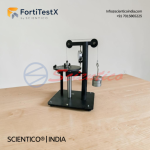
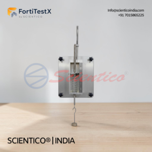
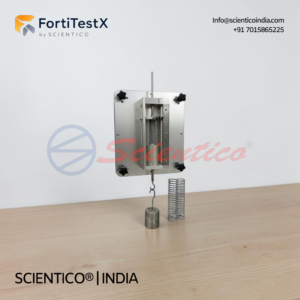
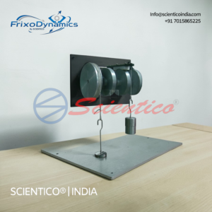
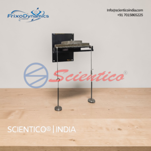
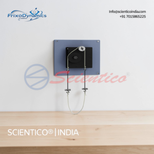
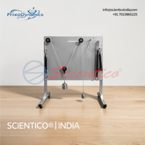
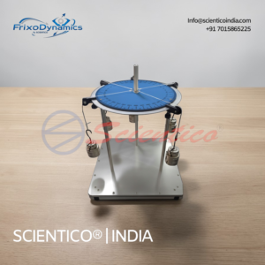
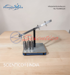
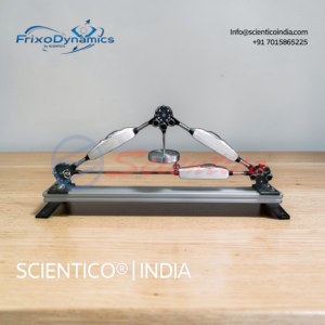
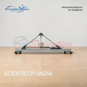
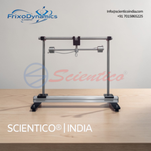
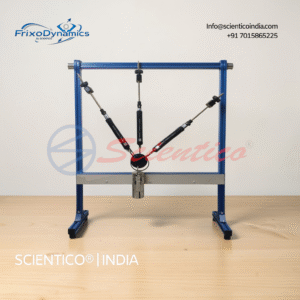
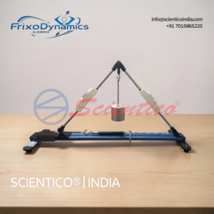
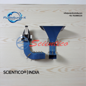
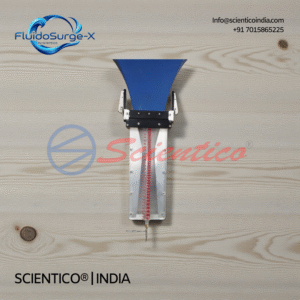
The FX-510 is used to measure the compressive force in the jib member and the tensile force in the tie member of a simple crane structure under applied loading. Students compare these measured values against theoretical predictions derived from the triangle of forces, verifying the principles of static equilibrium and concurrent force resolution in a physically recognisable structural context.

Q2: What is the triangle of forces, and how does the FX-510 demonstrate it?

The triangle of forces is a graphical method for determining the equilibrium of three concurrent forces acting at a point. When three forces are in equilibrium, they can be represented as the three sides of a closed triangle drawn to scale. The FX-510 demonstrates this by applying a known load at the jib-tie junction and measuring the resulting member forces. Students then construct a force triangle using the measured values and the known geometry, confirming that the triangle closes — verifying static equilibrium.

Q3: How are compressive and tensile forces measured on the FX-510?

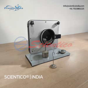
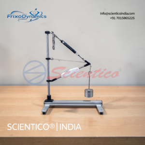
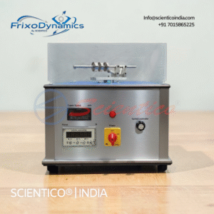
Tensile force in the tie member is measured using a spring balance integrated directly into the tie, with a range of 0–10 kg and a graduation of 50 g. Compressive force in the jib is measured using a force gauge integrated into the jib member, with a range of 0–100 N and a graduation of 0.5 N. Both instruments provide direct readings under load without requiring external measuring equipment.

Q4: Can the geometry of the crane be changed during experiments?

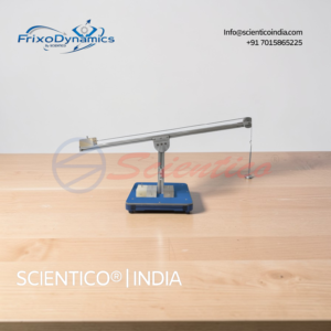
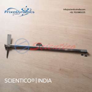
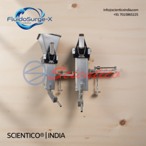
Yes. Both the jib overhang and the inclination of the tie member are adjustable by repositioning the member connections on the vertical support rod. This allows students to investigate how changes in the crane geometry affect the magnitude of forces in the two members, and to verify that the triangle of forces adapts correctly to each new configuration.

Q5: What is included in the scope of delivery for the FX-510?

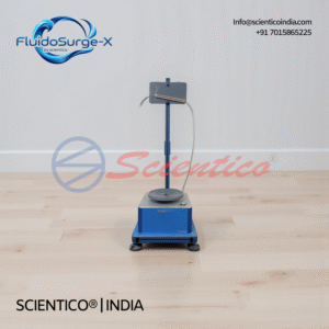
The FX-510 is supplied as a complete experimental kit including: one wall-mounted jib crane experimental unit; one integrated spring balance (tie member, 0–10 kg); one integrated force gauge (jib member, 0–100 N); one set of weights (4 x 2 kg, 1 x 1 kg, 1 x 1 N hanger); one hanger; one chain; one measuring tape/steel rule; and one instructional manual covering experimental procedures, force triangle construction, and data recording guidance.

You may also like

Lorem ipsum dolor sit amet, consectetur adipiscing elit, sed do eiusmod tempor incididunt ut labore et dolore magna aliqua. Ut enim ad minim veniam, quis nostrud exercitation ullamco laboris nisi ut aliquip ex ea commodo consequat.

Testimonials

Lorem ipsum dolor sit amet, consectetur adipiscing elit, sed do eiusmod tempor incididunt ut labore et dolore magna aliqua. Ut enim ad minim veniam, quis nostrud exercitation ullamco laboris nisi ut aliquip ex ea commodo consequat.

Subscribe to our newsletter

Lorem ipsum dolor sit amet, consectetur adipiscing elit, sed do eiusmod tempor incididunt ut labore et dolore magna aliqua.

    Make An Enquiry