Pressure Distribution in Journal Bearings Apparatus | FrixoDynamics FX-529

The SCIENTICO FrixoDynamics FX-529 Pressure Distribution in Journal Bearings Apparatus is a tribology unit for the direct visualisation and measurement of the circumferential pressure profile in a hydrodynamically lubricated journal bearing. A 50 mm stainless steel shaft runs within a 52.5 mm transparent open bearing shell, driven by a 200 W geared motor at continuously variable speeds from 0 to 200 rpm. Thirteen radial pressure tapping points around the bearing shell each connect to an individual tube manometer, displaying the full pressure distribution simultaneously as oil column heights up to 360 mm. The bearing gap is set precisely from 0 to 2.5 mm using a micrometer screw (0.01 mm graduation), and the spring plate shell mounting replicates self-aligning bearing behaviour. Students investigate pressure distribution as a function of speed, gap width, and load — including the bearing stability limit. Supplied with 0.5 L lubricating oil and comprehensive instructional material. Manufactured by SCIENTICO, available for institutional supply and international distribution.

The SCIENTICO FrixoDynamics FX-529 Pressure Distribution in Journal Bearings Apparatus is a specialised tribology unit for the direct visualisation of the radial pressure profile within a hydrodynamically lubricated journal bearing. Thirteen tube manometers measure the oil pressure at equally distributed points around the bearing shell circumference, displaying the pressure distribution as a set of readable liquid column heights. The bearing gap is adjustable via a micrometer screw from 0 to 2.5 mm, and shaft speed is continuously variable from 0 to 200 rpm via a 200 W geared motor. A fully transparent bearing shell allows direct observation of the lubricating film during operation. Manufactured by SCIENTICO, the FX-529 is suitable for supply to engineering institutions and distributors worldwide.

Product Overview
 

In a hydrodynamically lubricated journal bearing operating under load, the rotating shaft journal displaces the lubricant and generates a pressure distribution within the bearing gap that supports the shaft load without metal-to-metal contact. This pressure distribution is non-uniform around the bearing circumference — pressure builds up on the loaded side of the shaft and drops off on the unloaded side — and its magnitude and shape depend on the shaft speed, the bearing load, the lubricant viscosity, and the bearing gap width. Understanding this pressure distribution is fundamental to journal bearing design, lubrication system specification, and the analysis of bearing stability limits.

The FX-529 makes this pressure distribution directly visible and measurable. The apparatus features a 50 mm diameter stainless steel shaft running in a 52.5 mm internal diameter open bearing shell — a partial enclosure that simulates the journal bearing geometry while allowing pressure measurements to be taken around the full accessible circumference. Thirteen radial pressure measurement ports are distributed around the bearing shell, each connected to an individual glass or transparent tube manometer. As the shaft rotates and generates hydrodynamic pressure in the lubricant film, the oil columns in the manometers rise to heights corresponding to the local pressure at each measurement point, creating a direct visual representation of the circumferential pressure profile.

The bearing shell is mounted on two spring plates that allow it to move in response to the shaft load and hydrodynamic forces — replicating the self-aligning behaviour of a real bearing housing. The gap between the shaft and the bearing shell is adjusted using a radially movable bearing housing controlled by a micrometer screw with a range of 0–25 mm and a graduation of 0.01 mm, allowing the bearing gap to be set precisely between 0 and 2.5 mm. This gap adjustment capability is unique to the experimental setup and allows the effect of gap width on pressure distribution and bearing stability to be investigated systematically.

The 200 W geared motor drives the shaft at speeds continuously adjustable from 0 to 200 rpm, with the current speed shown on the display and control panel. Lubricating oil — 0.5 L supplied — circulates through the bearing gap, and the transparent bearing shell allows the lubricant film to be observed directly throughout the experiment. Students investigate how the pressure distribution changes with speed, bearing gap width, and load, and can identify the stability limit — the gap width below which the bearing transitions from stable hydrodynamic operation toward instability or contact.

Parameter Specification
Model FrixoDynamics FX-529
Shaft Diameter 50 mm
Shaft Length 50 mm
Shaft Material Stainless steel
Bearing Shell Internal Diameter 52.5 mm
Bearing Gap Range 0 – 2.5 mm
Bearing Shell Transparent, open (partial enclosure)
Bearing Shell Mounting Two spring plates — moveable
Pressure Measurement Points 13 radial points around bearing circumference
Pressure Display 13 tube manometers (oil column height)
Pressure Measurement Range 360 mm oil column
Bearing Housing Adjustment Micrometer screw, 0 – 25 mm range, 0.01 mm graduation
Motor Power 200 W geared motor
Speed Range 0 – 200 rpm (continuously adjustable)
Speed Display Digital display on control panel
Lubricant Oil, ISO VG class (0.5 L supplied)
Scope of Delivery 1 experimental unit, 1 x 0.5 L oil, 1 set of instructional material

Key Features

  • 13 radial pressure measurement points around the bearing shell circumference, each connected to an individual tube manometer — the full circumferential pressure profile is visible simultaneously without sensor repositioning
  • Transparent bearing shell allows direct visual observation of the lubricating film and hydrodynamic gap during operation
  • Micrometer screw bearing gap adjustment (0–25 mm range, 0.01 mm graduation) enables precise, repeatable gap width setting for systematic pressure distribution and stability experiments
  • Spring plate bearing shell mounting replicates the self-aligning behaviour of a real bearing housing under hydrodynamic and load forces
  • Continuously variable shaft speed 0–200 rpm with digital display for systematic speed-dependent pressure profile investigation
  • Pressure measurement range of 360 mm oil column provides adequate resolution for the full operating speed and gap range of the apparatus
  • 200 W geared motor delivers stable, consistent shaft speed for steady-state pressure distribution measurements
  • Compact, self-contained unit with rapid assembly onto the drive unit frame

Applications

  • Visualisation and measurement of the circumferential pressure distribution in a hydrodynamically lubricated journal bearing
  • Investigation of the effect of shaft speed on the radial pressure profile in the bearing gap
  • Investigation of the effect of bearing gap width on pressure distribution magnitude and profile shape
  • Study of the bearing stability limit as a function of gap width
  • Demonstration of the hydrodynamic pressure support mechanism — how the lubricant film carries the shaft load without metal contact
  • Comparison of pressure distributions at different load and speed combinations
  • Undergraduate and postgraduate laboratory practicals in tribology, machine elements, lubrication engineering, and mechanical engineering design
  • Supplementary demonstration for courses covering hydrodynamic bearing theory, Reynolds equation, and bearing design

Construction and System Design

The FX-529 is designed for rapid assembly onto a drive unit frame, with all major components — motor, shaft, bearing shell assembly, manometer bank, and control panel — arranged in a compact, accessible layout. The 200 W geared motor is coupled to the 50 mm stainless steel shaft through the frame, driving the shaft at speeds set and displayed via the control panel. The shaft runs within the open bearing shell, which partially encloses it to simulate the journal bearing geometry.

The bearing shell is secured in a radially movable housing supported by two spring plates. The spring plate mounting allows the shell to deflect slightly under hydrodynamic and load forces, as a real bearing housing would. The micrometer screw on the housing provides fine, graduated radial positioning of the shell relative to the shaft axis, setting the bearing gap with 0.01 mm resolution. The gap is confirmed by direct micrometer reading, not inferred from motor parameters, ensuring precise gap setting for each experiment condition.

Thirteen pressure tapping ports are distributed around the bearing shell circumference at defined angular intervals. Each port is connected via a small-bore tube to one of the 13 tube manometers mounted on a vertical panel beside the apparatus. As hydrodynamic pressure builds in the bearing gap, oil is forced into the manometer tubes, and the column heights provide a direct, visual, and quantitative representation of the local pressure at each angular position. The pressure profile across all 13 points is readable simultaneously, allowing the full circumferential pressure distribution to be recorded at any operating condition without repositioning any sensor.

The transparent bearing shell allows the lubricant meniscus and film condition to be observed directly during operation. Lubricating oil is supplied to the bearing via the included 0.5 L quantity, with the system designed for recirculation or replenishment as required during the experiment programme.

Export and Supply Capability

The SCIENTICO FrixoDynamics FX-529 is available for supply to engineering colleges, technical universities, mechanical engineering departments, research institutions, and industrial training centres. SCIENTICO manufactures and exports laboratory equipment to institutions and distributors across multiple regions. Standard packaging is suitable for international shipment. Bulk orders, customised configurations, and institutional procurement enquiries are welcomed. Please contact SCIENTICO directly for pricing, lead times, and shipping terms.

Q1: What does the pressure distribution in journal bearings apparatus demonstrate?

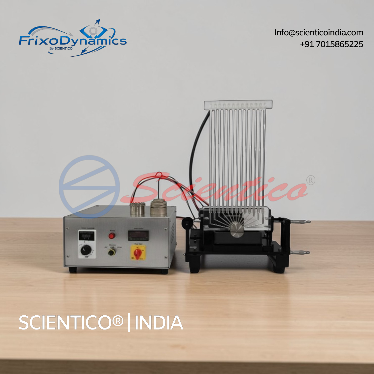
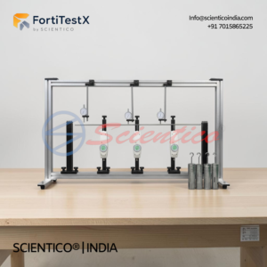
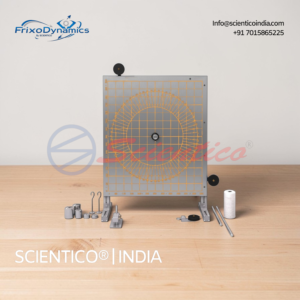
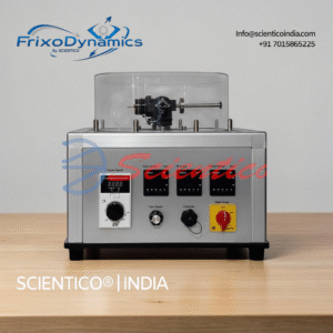
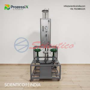
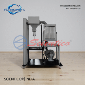
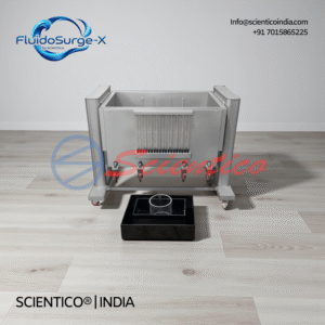
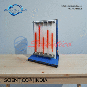
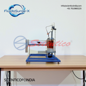
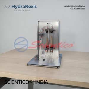
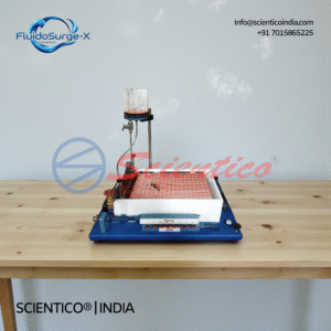
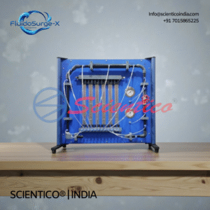
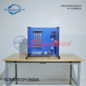
The FX-529 demonstrates how a rotating shaft journal generates a non-uniform pressure distribution within the lubricating film of a hydrodynamic journal bearing. The pressure rises on the loaded side of the shaft as the lubricant is drawn into the converging gap between the shaft and bearing shell, and it falls on the unloaded side. The 13 tube manometers display this pressure profile simultaneously around the full circumference, making the hydrodynamic support mechanism directly visible and quantifiable.

Q2: How does shaft speed affect the pressure distribution in the FX-529?

As shaft speed increases, the hydrodynamic effect strengthens — the rotating shaft pumps more lubricant into the converging gap, generating higher pressures. Students observe that the peak oil column height in the manometers increases with speed, and that the asymmetry of the pressure profile — with higher pressure on the loaded side and lower on the other — becomes more pronounced. This directly demonstrates the speed dependency of hydrodynamic bearing load capacity.

Q3: What is the bearing stability limit, and how is it investigated on the FX-529?

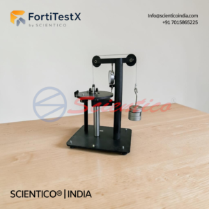
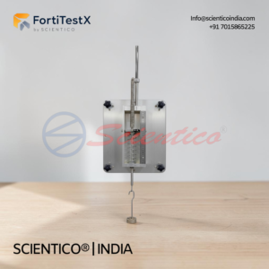
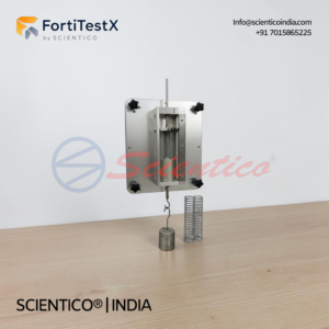
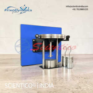
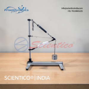
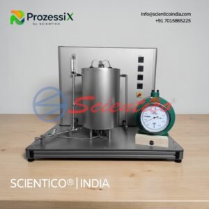
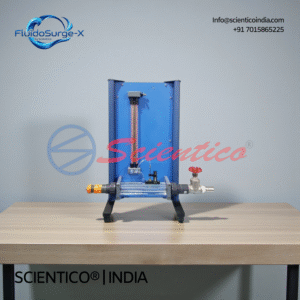
The bearing stability limit is the minimum bearing gap width at which stable hydrodynamic operation can be maintained. As the gap is reduced below a critical value, the pressure distribution can become asymmetric to a degree that causes the shaft to be pushed further toward the shell wall rather than self-centering — a condition of instability that can lead to contact. The FX-529 allows the gap to be reduced in controlled steps using the micrometer screw, and students can observe the changes in pressure profile and shaft behaviour as the stability limit is approached.

Q4: Why are tube manometers used instead of electronic pressure sensors on the FX-529?

Tube manometers provide a simultaneous, visual, real-time display of all 13 pressure values without any electronic instrumentation, calibration, or signal processing. The oil column heights are directly proportional to the local gauge pressure at each tapping point and can be read and recorded immediately. This makes the full circumferential pressure profile visible at a glance — a significant pedagogical advantage for demonstrating the pressure distribution concept compared to reading 13 separate digital values. The 360 mm oil column measurement range is appropriate for the pressure levels generated in this apparatus at operating speeds up to 200 rpm.

Q5: What is included in the scope of delivery for the FX-529?

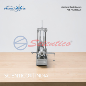
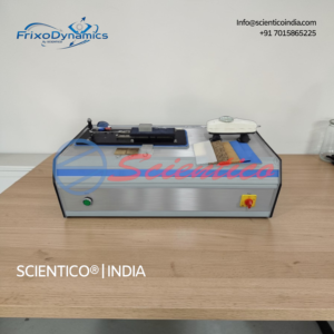
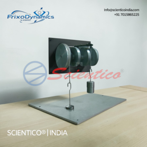
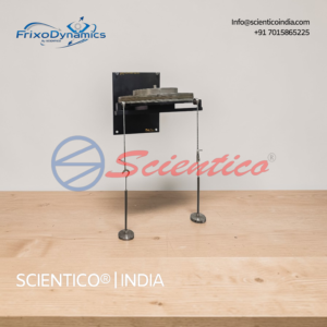
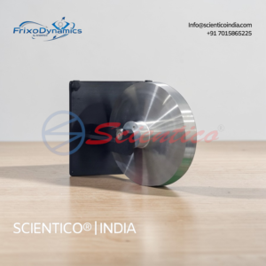
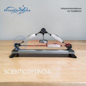
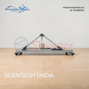
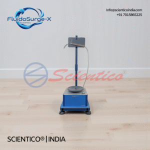
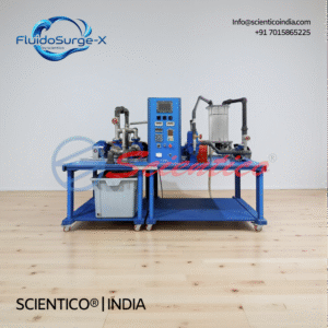
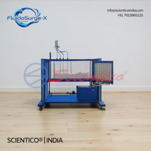
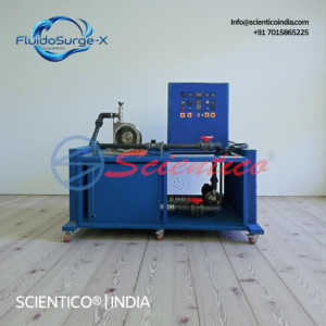
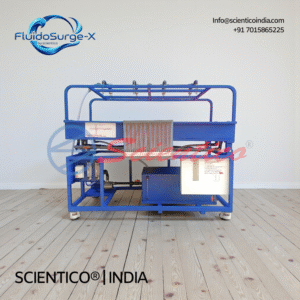
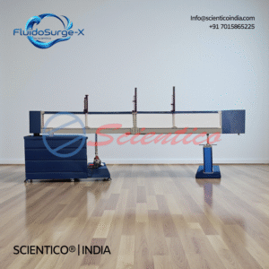
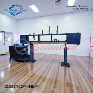
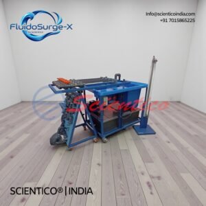
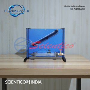
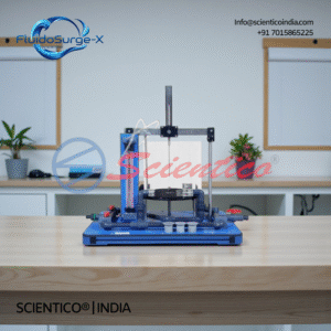
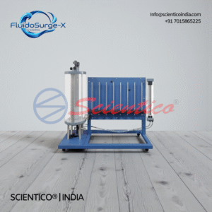
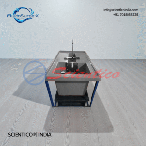
The FX-529 is supplied as a complete unit including: one pressure distribution experimental unit with 50 mm stainless steel shaft, transparent open bearing shell on spring plate mounting, micrometer-adjustable bearing housing, 13-point circumferential pressure tapping system, 13 tube manometers, 200 W geared motor with continuously variable speed control, and digital speed display; one 0.5 L quantity of lubricating oil; and one set of comprehensive instructional material covering assembly, experimental procedures, theory, and data recording guidance.

You may also like

Lorem ipsum dolor sit amet, consectetur adipiscing elit, sed do eiusmod tempor incididunt ut labore et dolore magna aliqua. Ut enim ad minim veniam, quis nostrud exercitation ullamco laboris nisi ut aliquip ex ea commodo consequat.

Testimonials

Lorem ipsum dolor sit amet, consectetur adipiscing elit, sed do eiusmod tempor incididunt ut labore et dolore magna aliqua. Ut enim ad minim veniam, quis nostrud exercitation ullamco laboris nisi ut aliquip ex ea commodo consequat.

Subscribe to our newsletter

Lorem ipsum dolor sit amet, consectetur adipiscing elit, sed do eiusmod tempor incididunt ut labore et dolore magna aliqua.

    Make An Enquiry